TouchDesigner Tutorial: POPs Audio Reactive
10-28-2025
Motivation and Starting point
Since this will be my first formal TouchDesigner tutorial, I want to set the stage for what to expect. In terms of frequency, readers shouldn’t expect these tutorials to come out often or follow any kind of regular schedule they’ll be created as I have the time and interest. This tutorial assumes beginner-level experience with TouchDesigner.
A fellow developer at ART-CLUB mentioned that the club could use more dark visuals rather than the bright and loud ones we usually see. I agreed so this tutorial is the result of my attempt to create darker, moodier visuals.
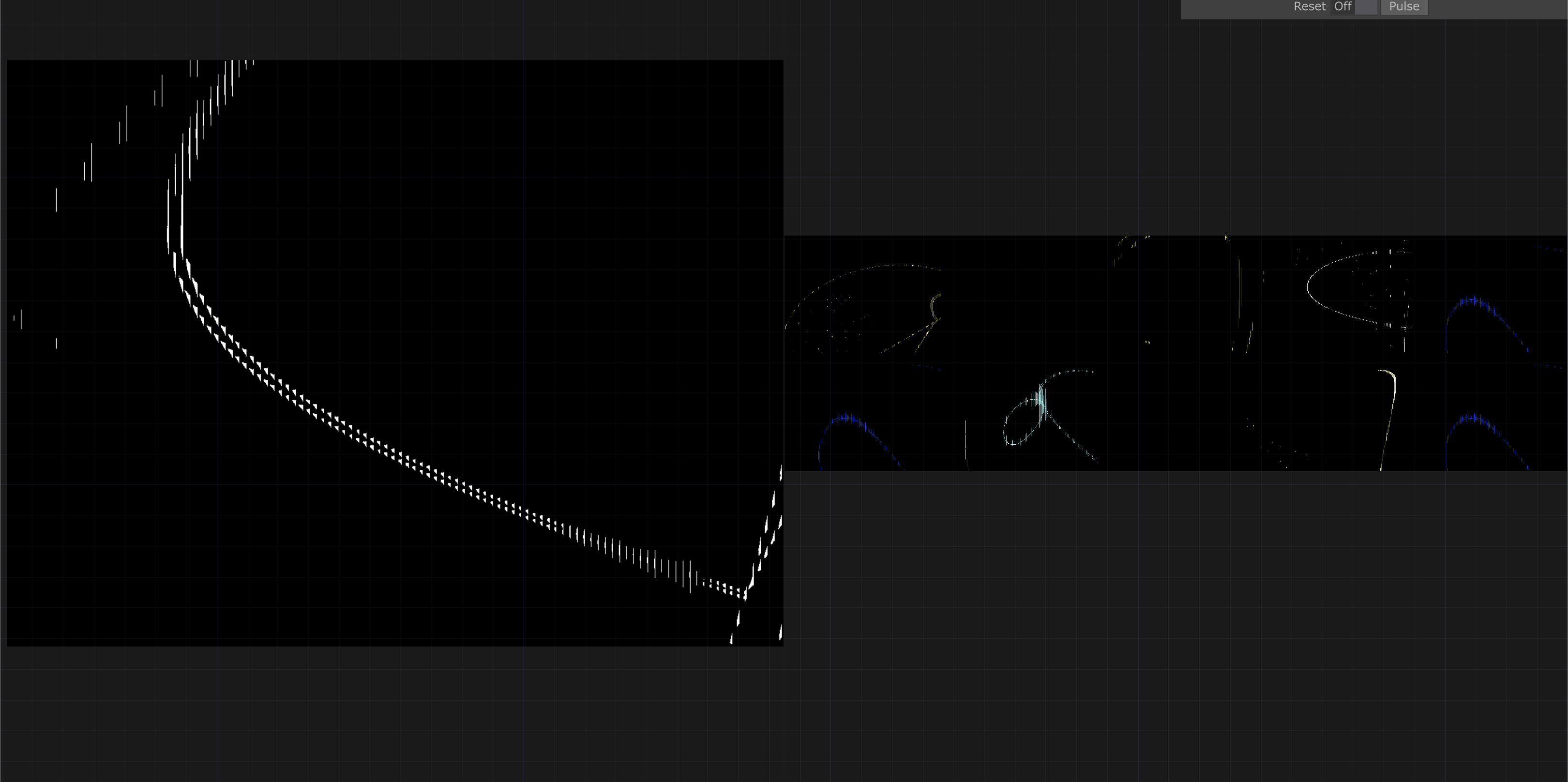
For this tutorial, I’ll be using TouchDesigner (TD) Experimental version 2025.31310. We’ll be creating the following visual, which leverages TD’s newest operator family: POPs.
 |
|---|
| Final Result |
Geometry
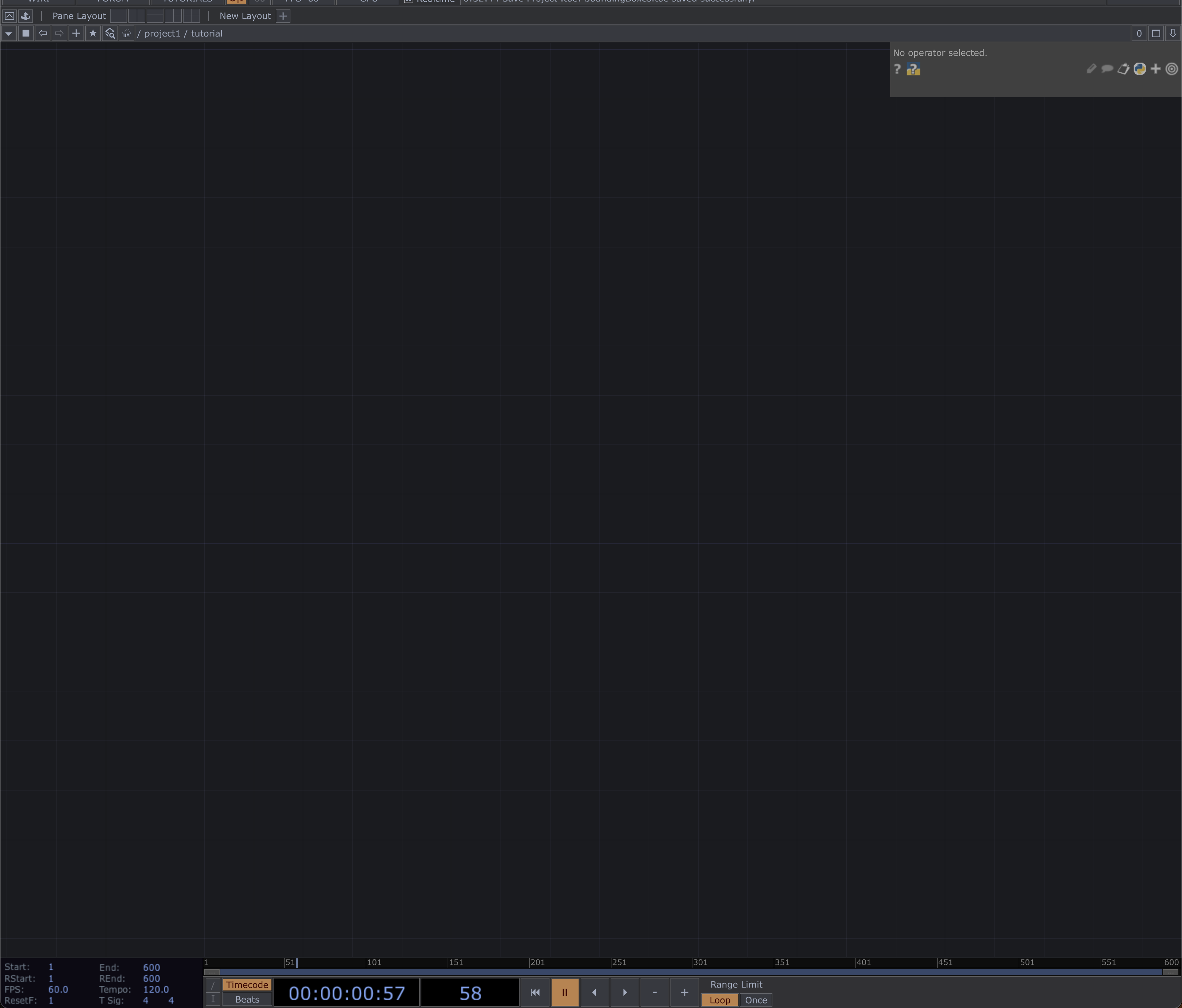
First things first whenever you open TouchDesigner (TD), a starter project template will automatically load. Delete this, as none of the default nodes will be used for this tutorial.
Your workspace should now look like this:
 |
|---|
| Blank TD Project |
Since this tutorial is focused on showcasing POPs, let’s begin with the geometry.
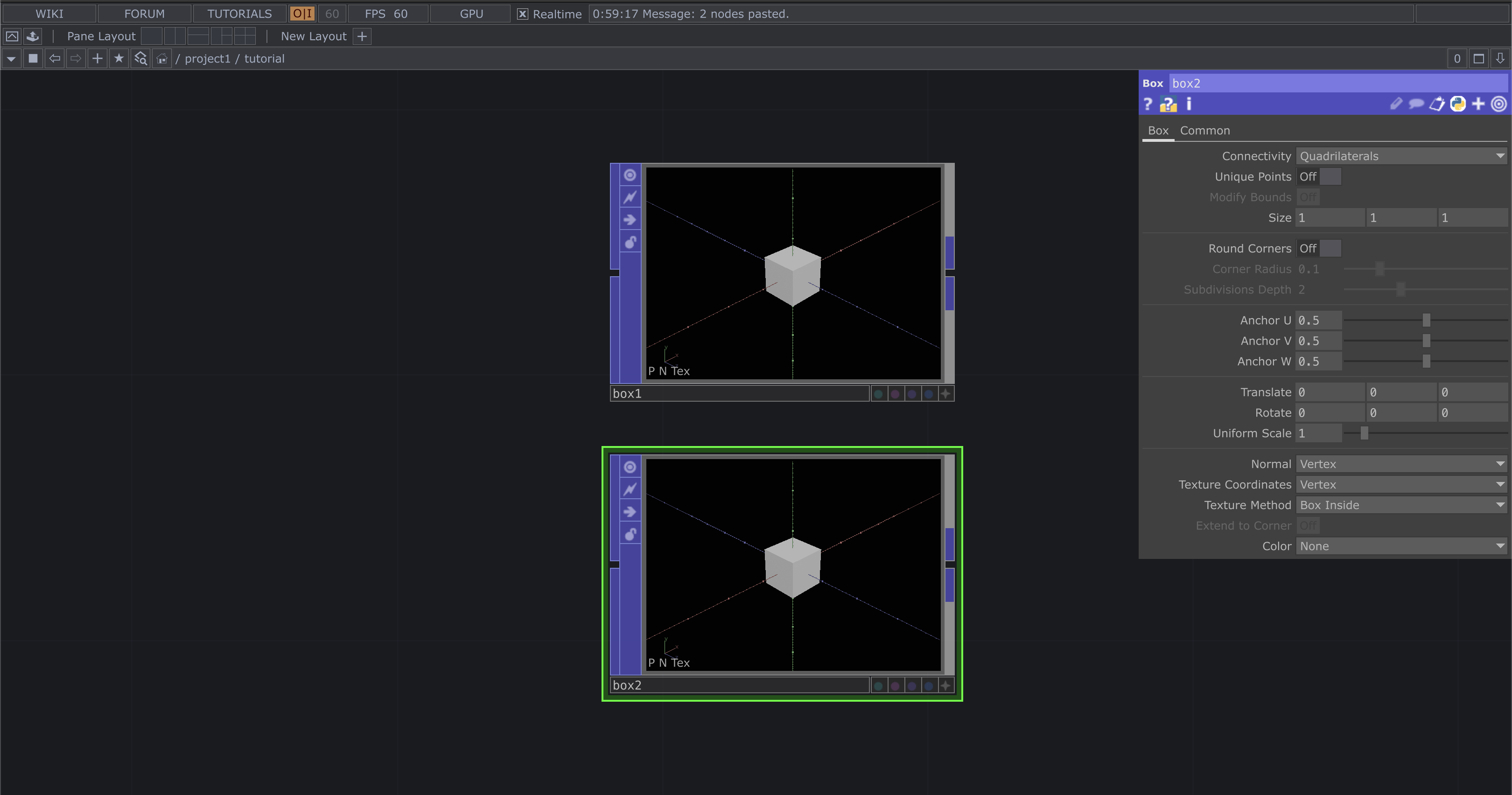
Start by creating two Box POPs, their names will be automatically generated as box1 and box2.
 |
|---|
| Box POPs |
There are a lot of parameters here, and toward the end of the tutorial, I’ll highlight a few that are fun or useful to experiment with. For now, don’t change anything about the default setup. Now:
- Tap the TAB key, a menu will appear. Keep pressing TAB until you land on the POPs page.
- Type transform. As you type, most options will fade out until only a few remain.
- Select the operator called Transform, then connect the output of box1 to the input of transform1.
- Repeat the same steps for box2.
 |
|---|
| Creating Transform Network |
Create Null nodes for each branch of the network we’re building.
Both box1 and box2 should each have a Transform node and a Null node linked to them, forming two parallel strands in your network.
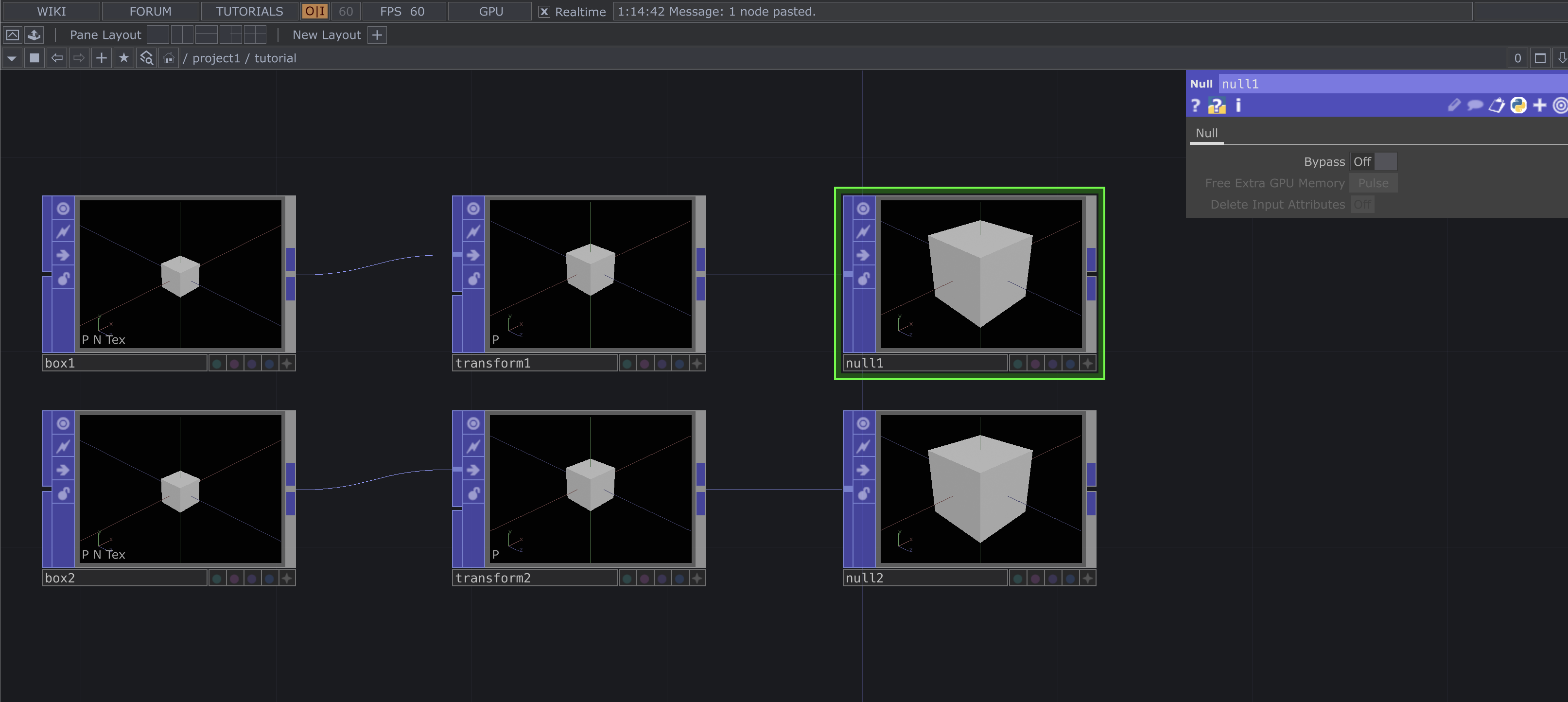 |
|---|
| Adding Nulls |
Copy and Paste these 3 nodes and change the parameters to match those shown further below this will be out third box in the geometry POP chain.
 |
|---|
| Adding Box 3 |
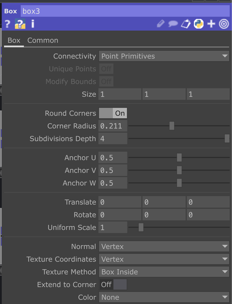 |
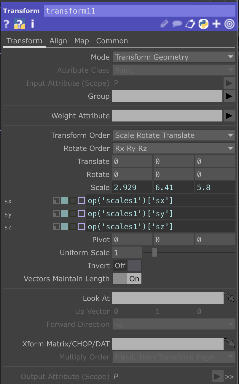 |
|---|---|
| Params For Box 3 | Params For Transform 3 |
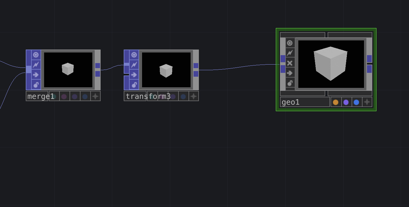
Finally, to complete this geometry network, we’re going to merge the two boxes into a single geometry and then add a Transform node to the merged output.
Adding the Transform at the end of the network gives us extra versatility, it lets us manipulate both the combined geometry and the individual boxes independently. (This will come into play later.)
It may look like there’s only one box now, that’s totally fine. We’ll adjust this later in the tutorial.
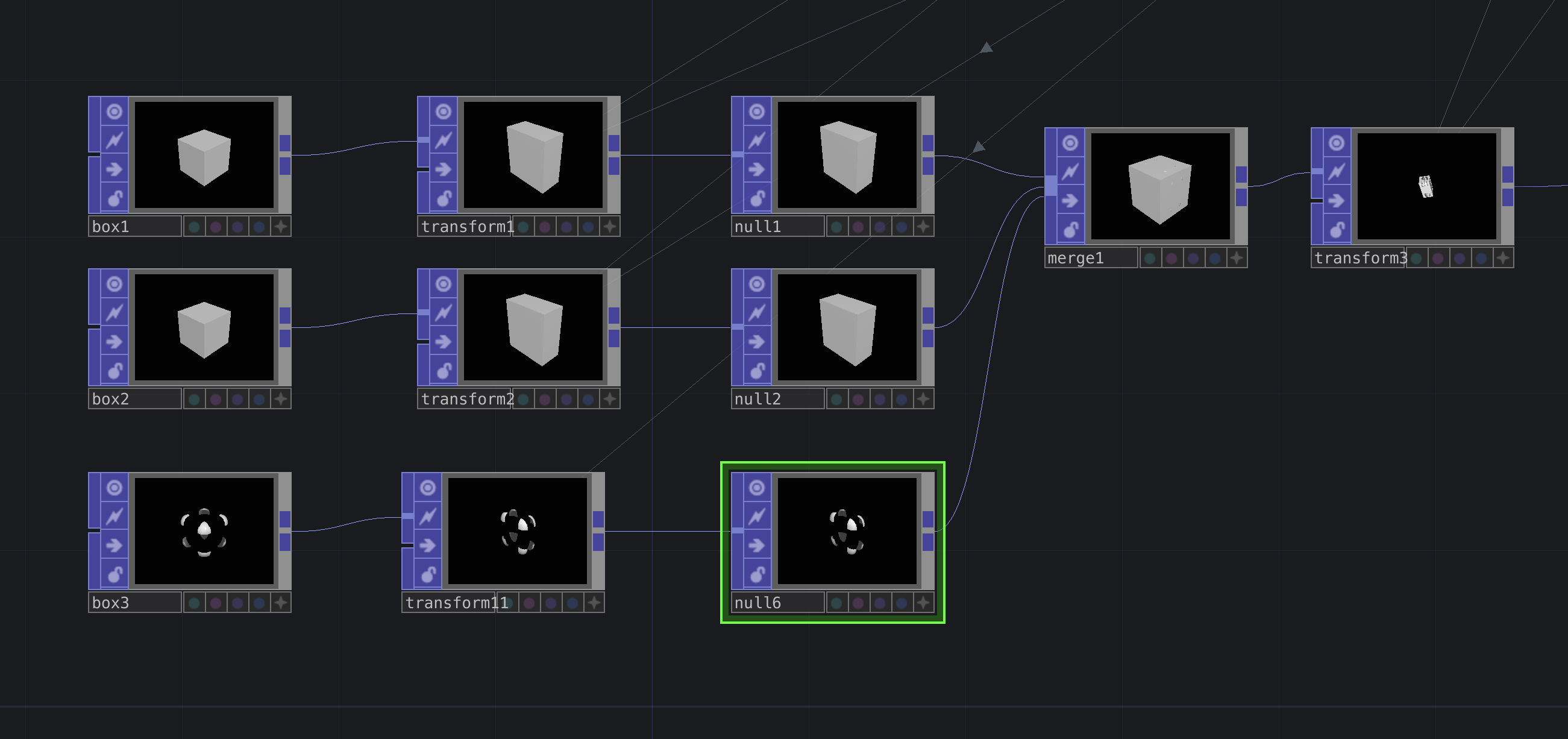 |
|---|
| Finishing Geometry |
Transformation and Reactivity
For this next section, we’ll be adding the values needed to bring in movement and audio reactivity. Things might get a little confusing here and if they do, I apologize! Feel free to message me on Instagram if you have any questions.
This part of the tutorial relies on a custom component I created for analyzing audio. You can download it here.
The link will take you to a Google Drive folder where you can find my custom audio analysis tool called smallAudioAna.tox.
Once downloaded, drag this file into your workspace in TouchDesigner.
 |
|---|
| Audio Analysis Tool |
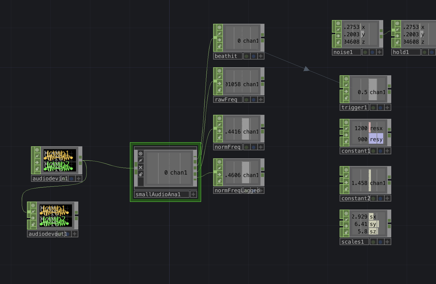
Notice that smallAudioAna.tox has four outputs and one input. This means the component takes in an audio signal and outputs four different frequency bands or analysis channels.
Create four Nulls and connect each of the outputs from smallAudioAna.tox to its corresponding Null. Make sure these Nulls come from the CHOP category when you press TAB.
In addition, smallAudioAna.tox needs an audio input. You can use your computer or laptop’s built-in microphone for this. If you don’t hear anything, it’s likely because there’s no audio output device set up, just add an Audio Device Out CHOP to fix that.
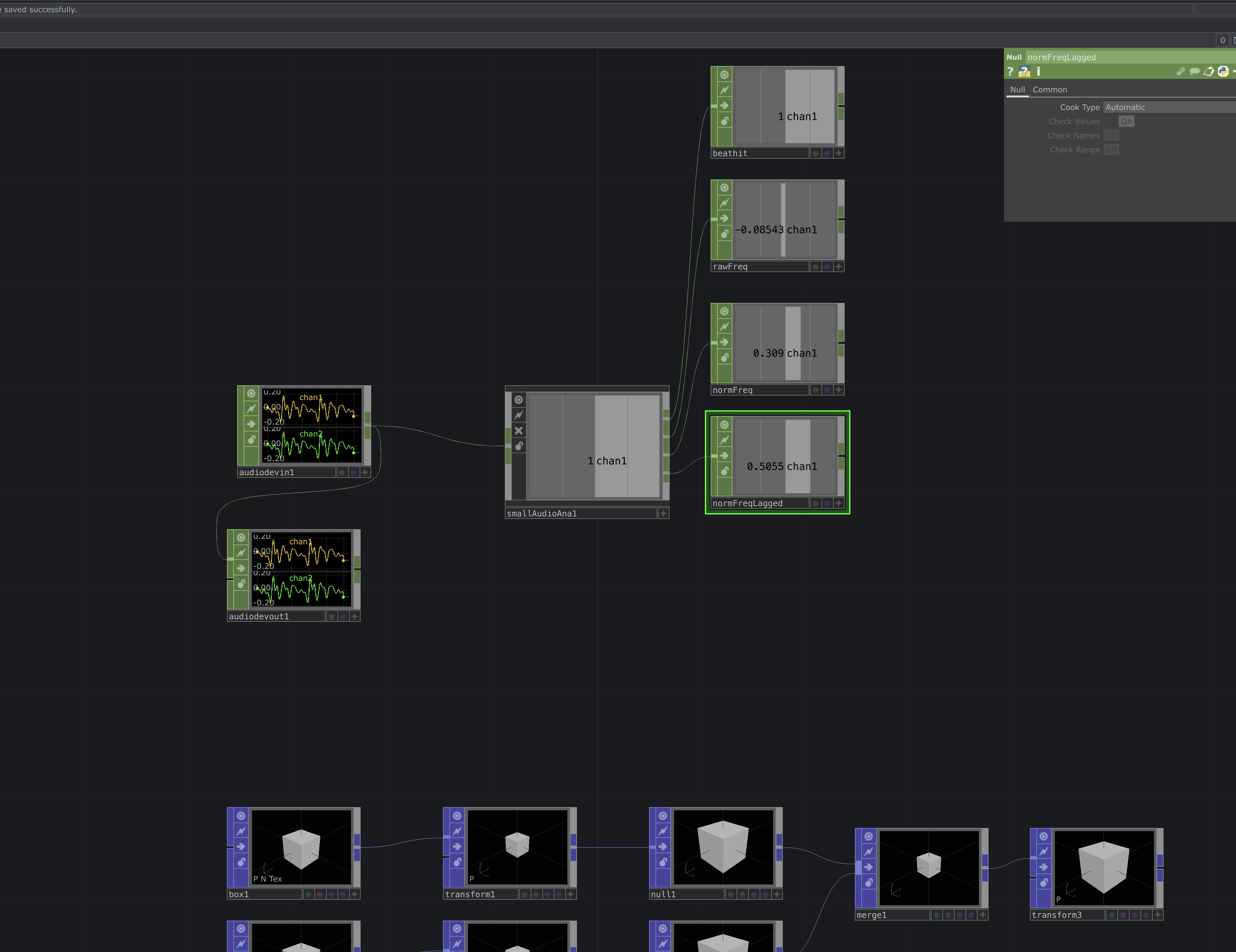 |
|---|
| Node Network After Audio |
From top to bottom, each of the Null CHOPs connected to the audio component represents the following:
- beathit – Triggers every time the audio frequency goes above a certain threshold. Outputs binary values (0 or 1).
- rawFreq – A floating-point value showing the raw incoming audio signal (usually small values).
- normFreq – The same as rawFreq, but normalized to a range between [0–1].
- normFreqLagged – The same as normFreq, but with a small lag added for smoother transitions.
Next, create a noise CHOP, make sure the channel and common settings are configured as shown below.
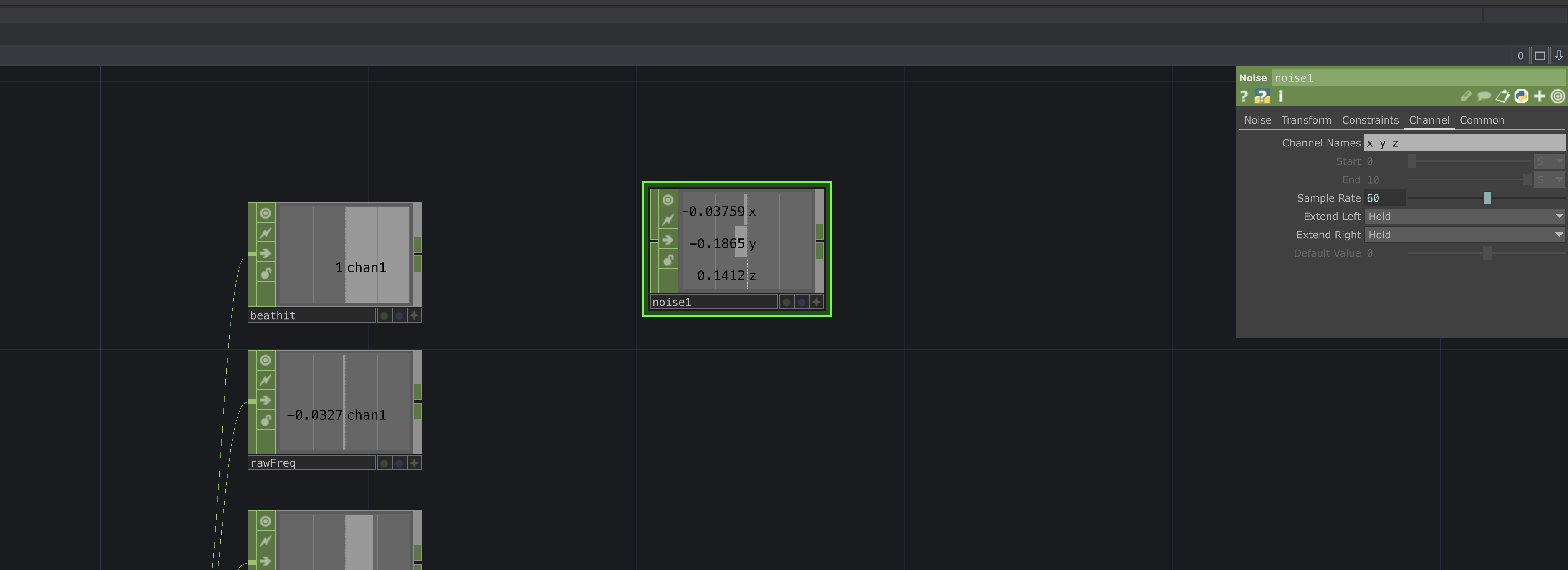 |
|---|
| Channels |
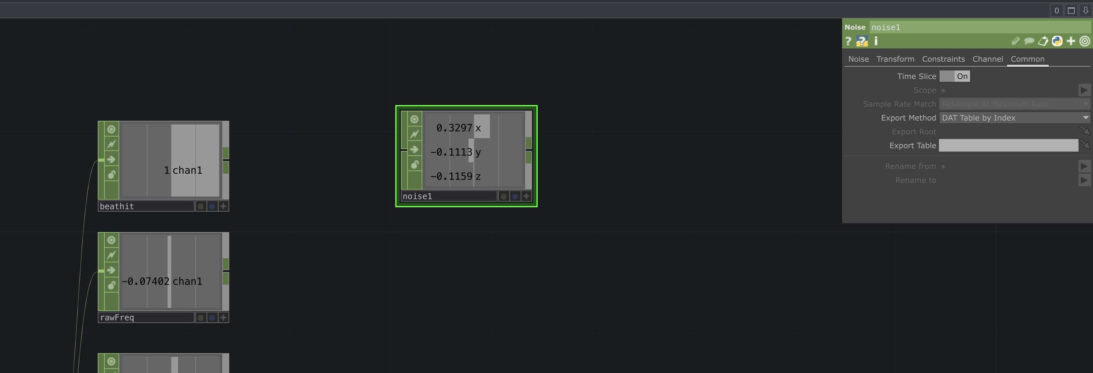 |
|---|
| Common |
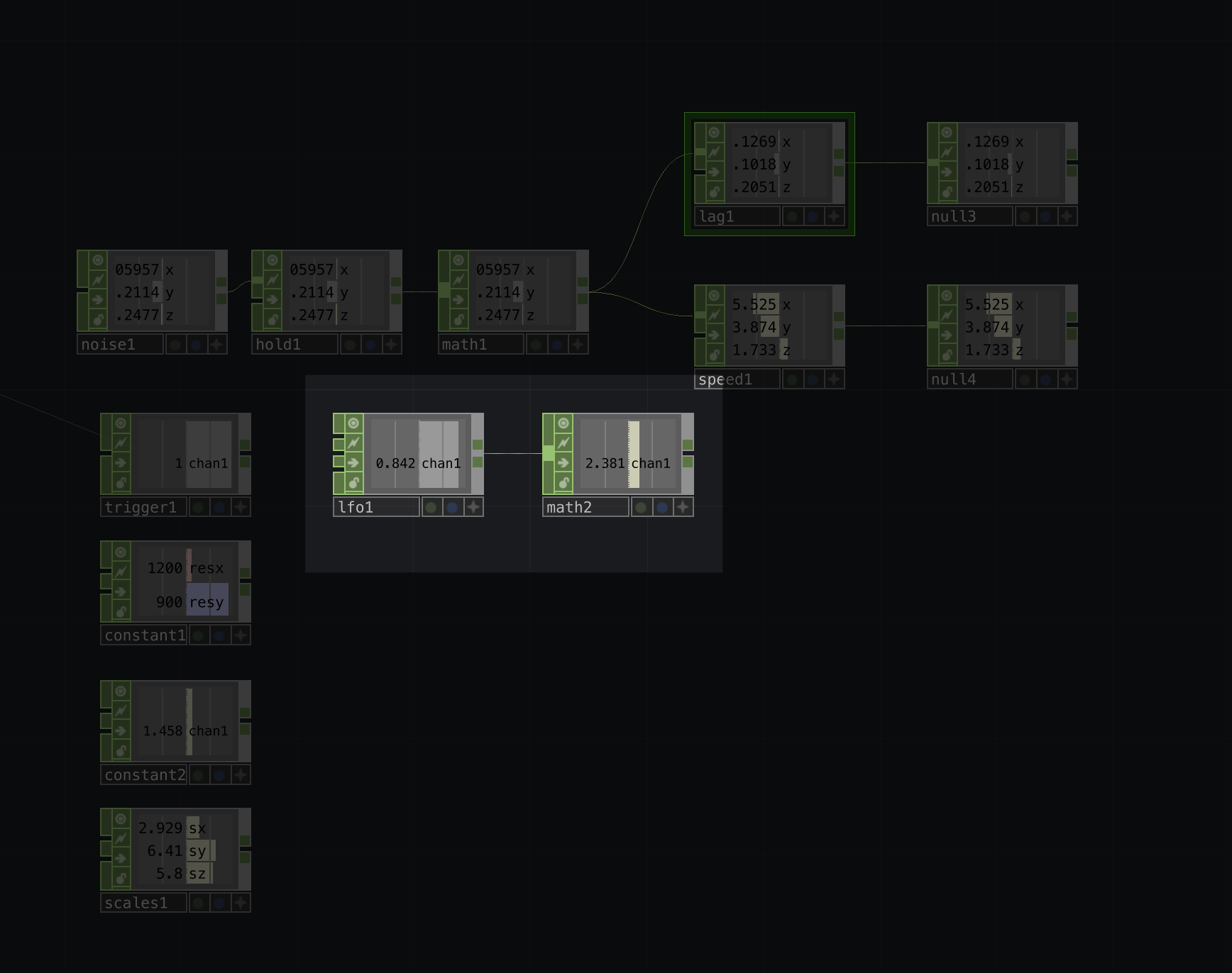
Create the following chain of nodes, this chain will let us generate continuous movement that stays in step with the incoming audio:
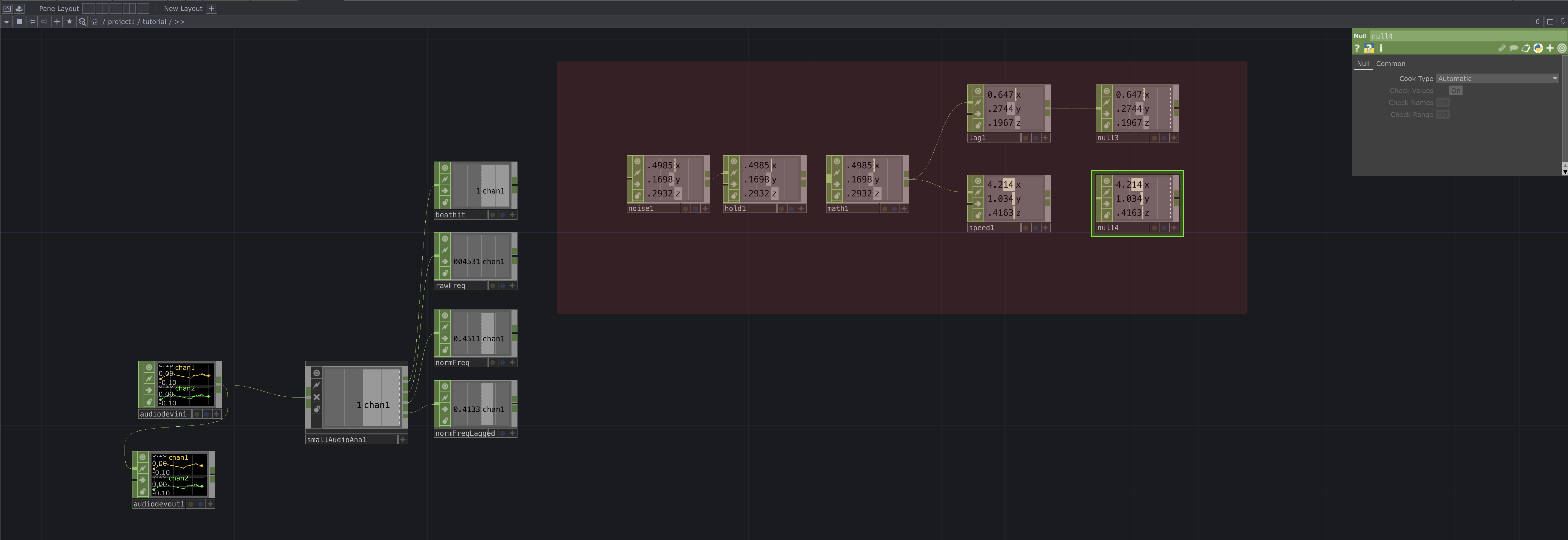 |
|---|
| Audio Chain |
Here are the settings to apply to each node, from left to right:
hold1- Set Sample to While Off
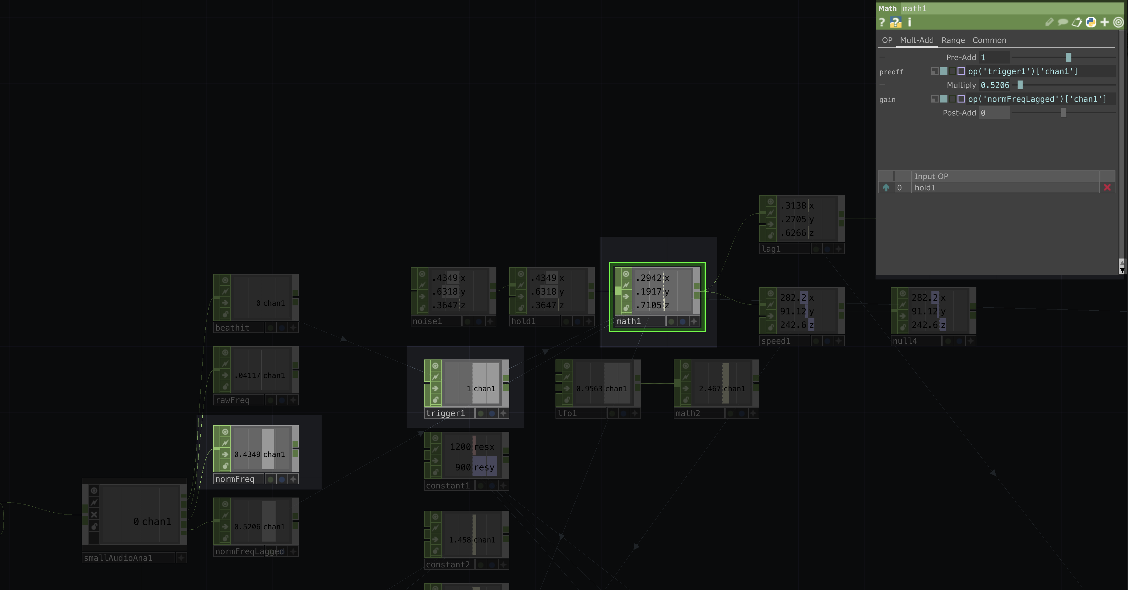
math1- (no changes)
lag1- (no changes)
speed1- (no changes)
Now we’ll continue to parameterize:
- Create a
triggerCHOP and enter the following in its Trigger parameter:op('beathit')['chan1'] - Copy the settings shown in the photos below.
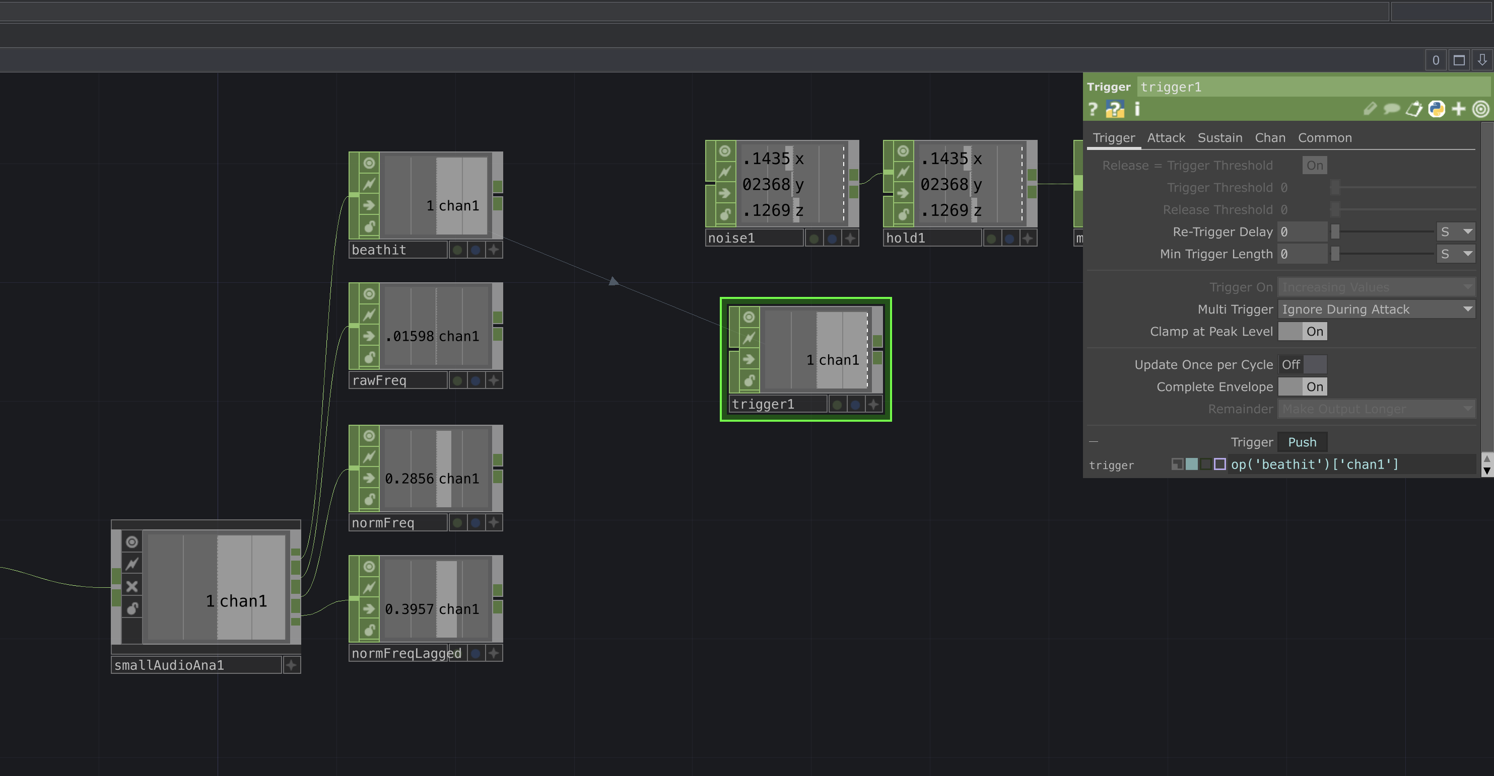 |
|---|
| Trigger |
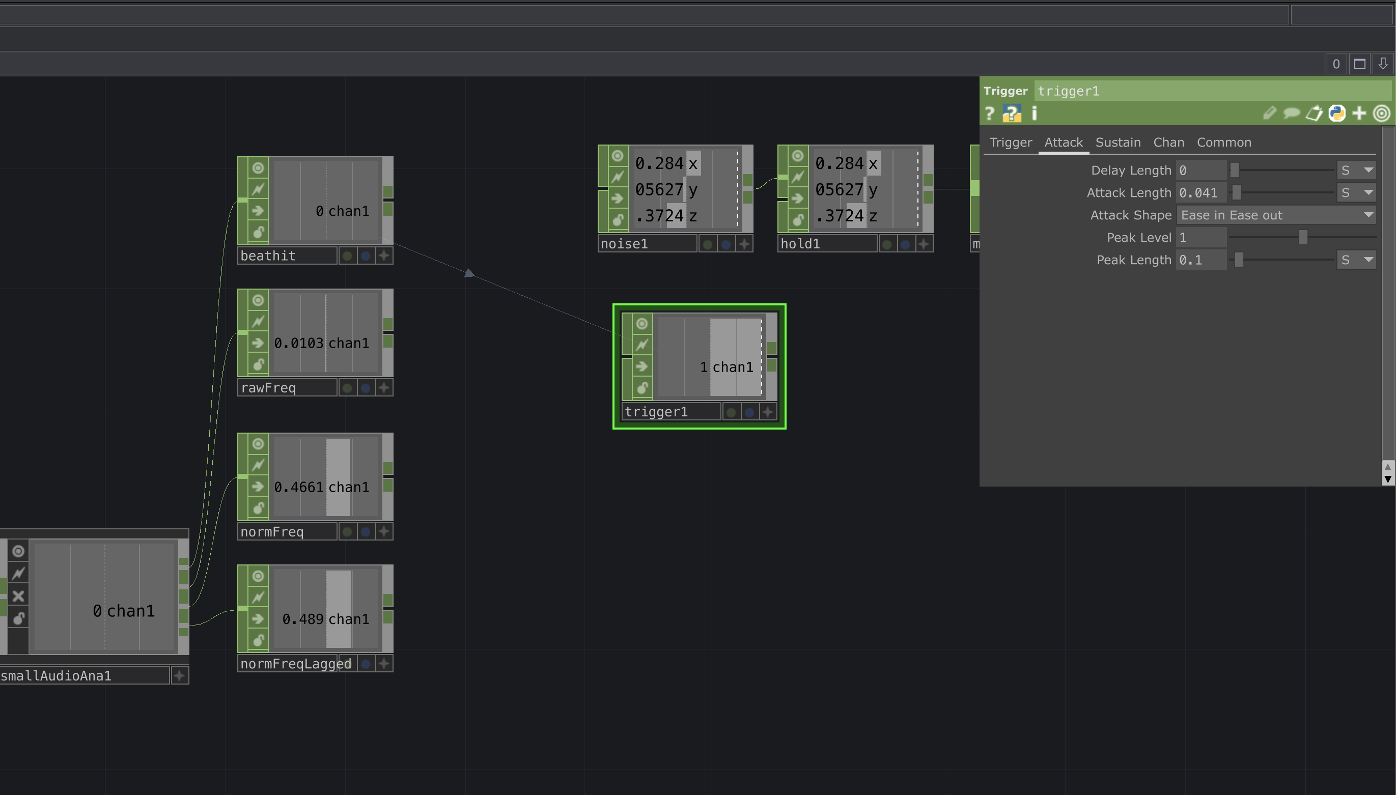 |
|---|
| Attack |
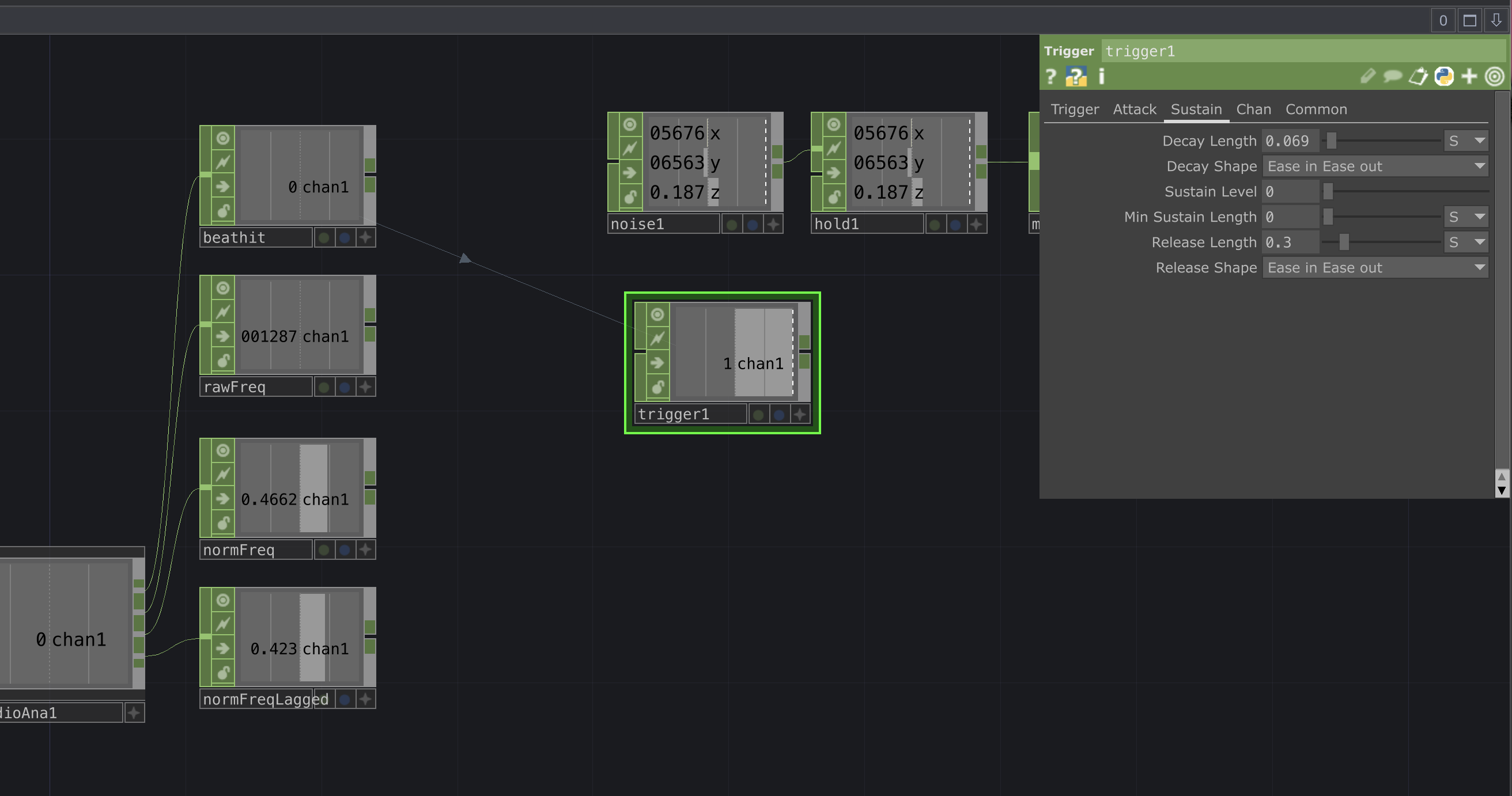 |
|---|
| Sustain |
Constants
Create a Constant CHOP with two channels
[resx, resy], and set their values to[1080, 1080]respectively. Name this nodeconstant1.Create another Constant CHOP and set its single value to
1.458. It should automatically be namedconstant2.Create a third Constant CHOP with three channels
[sx, sy, sz], and set their values to[2.929, 6.41, 5.8]. Name this nodescales1.
 |
|---|
| Constants |
Low frequency Oscillator
Lastly, we’ll add a Low-Frequency Oscillator (LFO CHOP) and scale its output using a Math CHOP.
Create an LFO CHOP with the following parameters:
| Type | Play | Frequency | Offset | Amplitude | Bias | Phase |
|---|---|---|---|---|---|---|
| Triangle | On | 3.044 | 0 | 1 | 0 | 0 |
Connect this LFO to a Math CHOP with the following parameters:
| From Range | To Range |
|---|---|
| [-1,1] | [1,2.5] |
 |
|---|
| LFO |
Render Network and Materials
Go back to the last Transform POP in your network.
Click and drag its output, then press TAB to open the operator menu.
Navigate to the COMP section and select the Geometry node.
Your network should now look like this:
 |
|---|
| Goemetry Node |
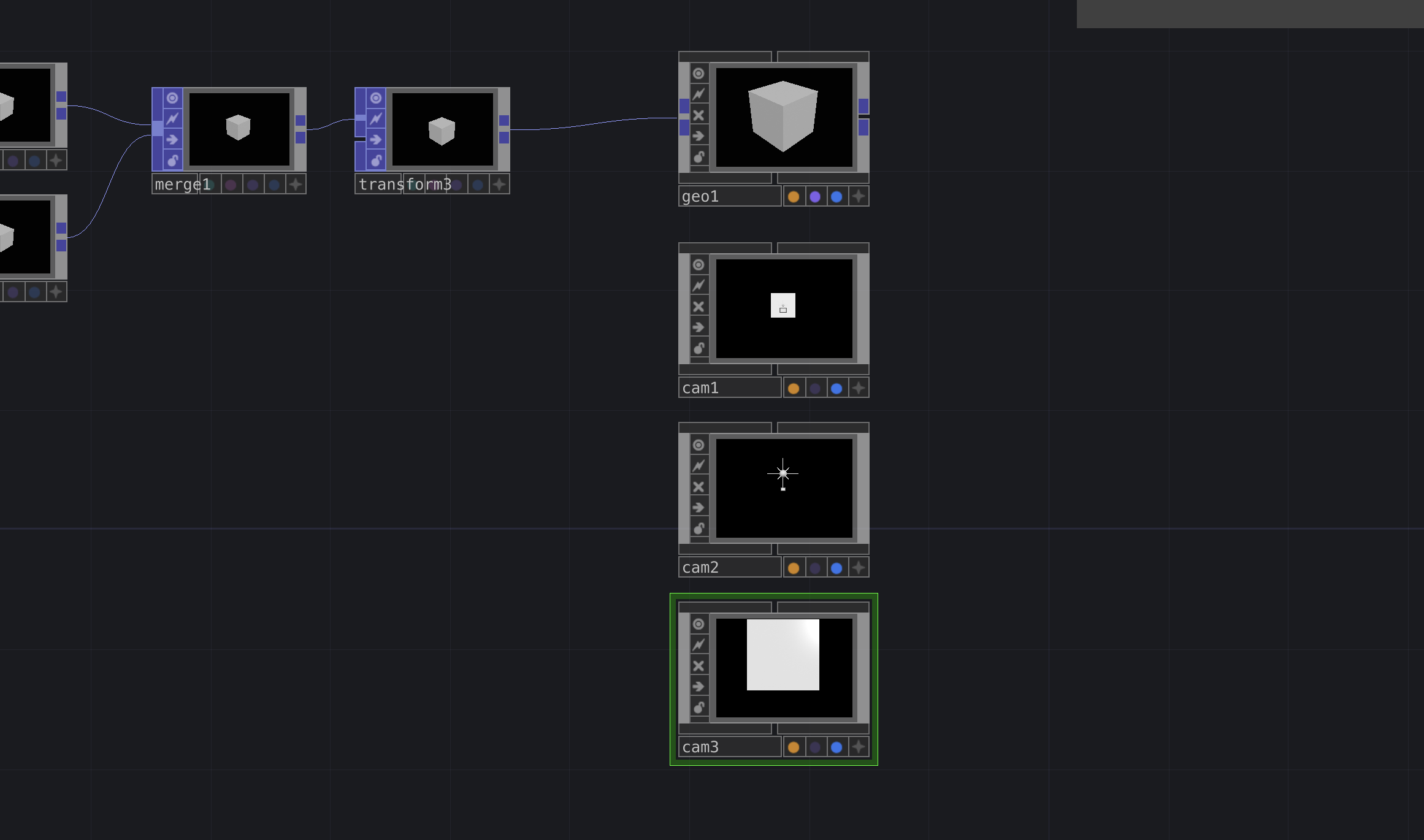
In any render network, we’ll need cameras, this project requires three, each set at different distances.
To create them, press TAB to bring up the operator palette, navigate to the COMP section, and select Camera.
Repeat this process three times.
You should end up with something like this:
 |
|---|
| Cameras |
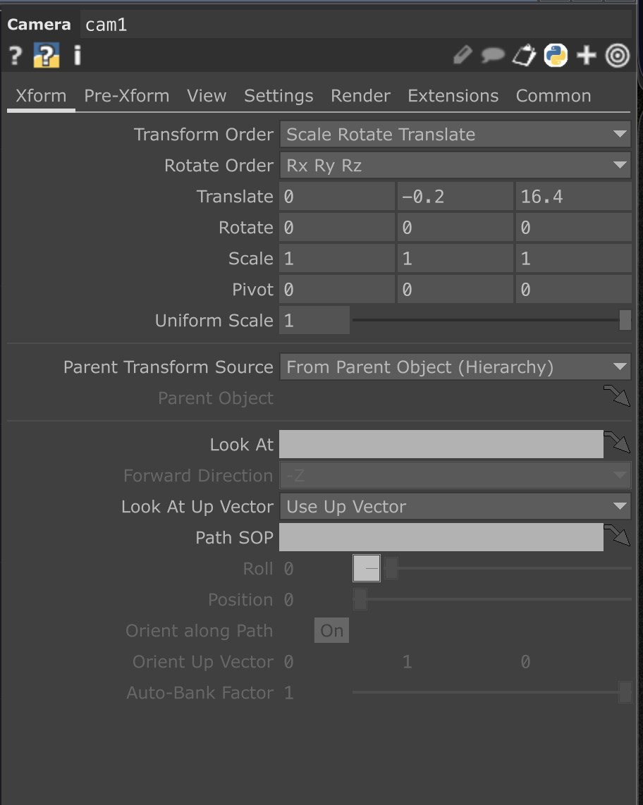
Each camera will have different parameters:
 |
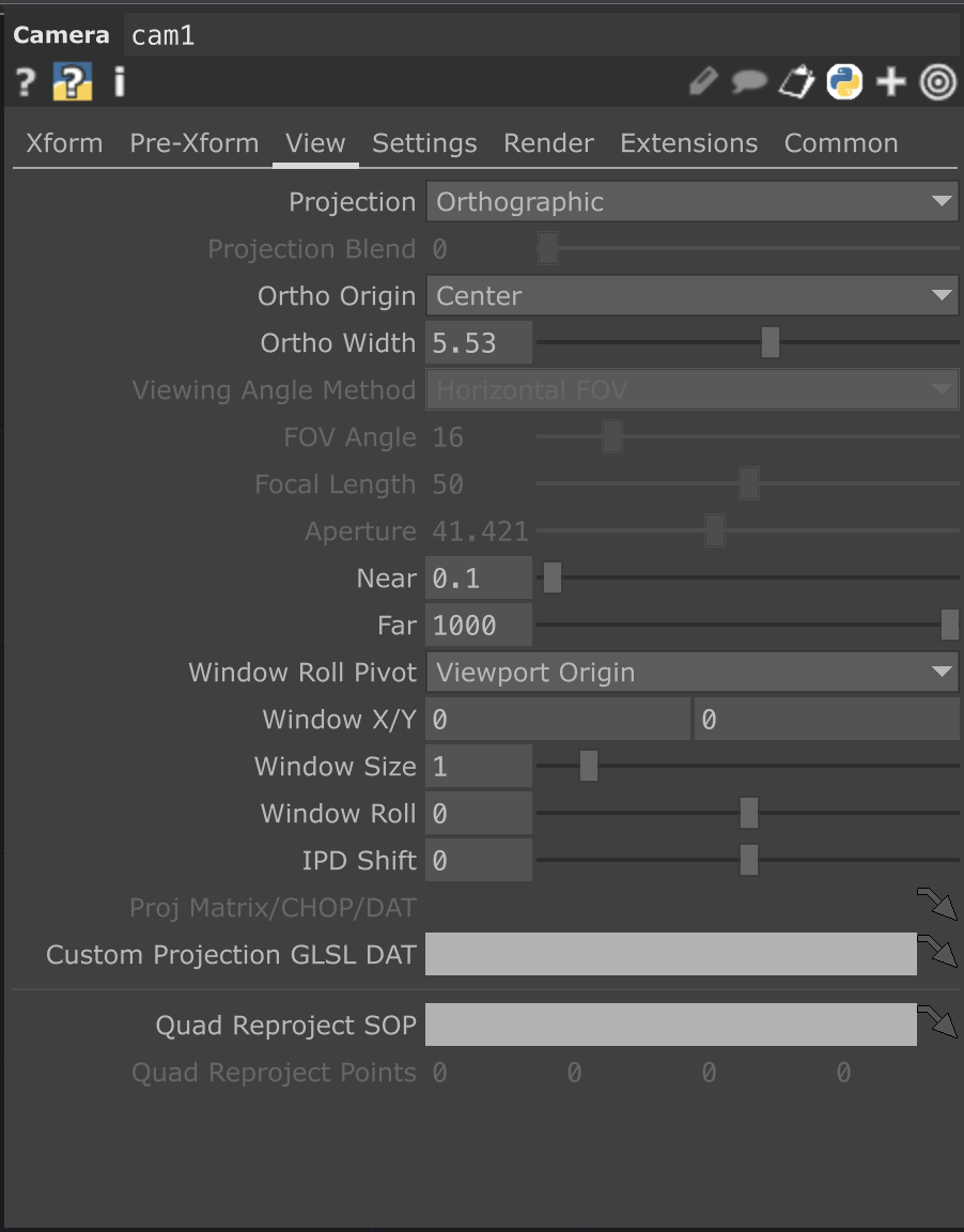 |
|---|---|
| CAM1 XForm | CAM1 View |
 |
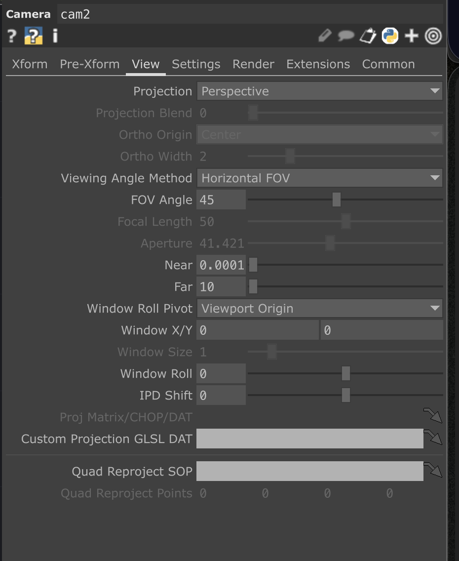 |
|---|---|
| CAM2 XForm | CAM2 View |
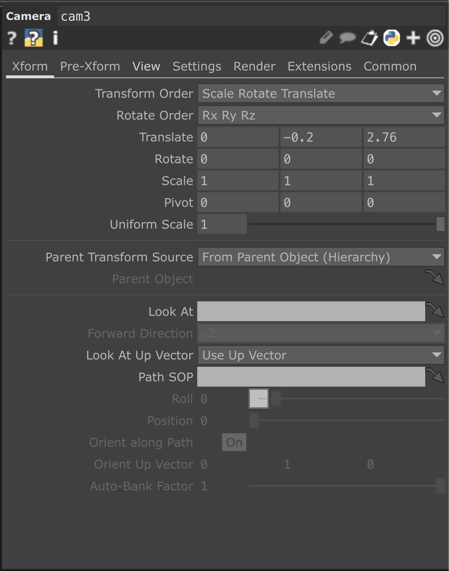 |
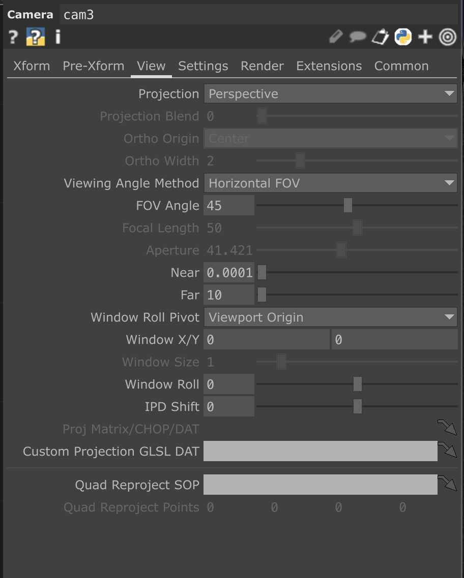 |
|---|---|
| CAM3 XForm | CAM3 View |
Next, open the operator palette again by pressing TAB, navigate to the COMP section, and create three Light operators.
Your setup should now look like this:
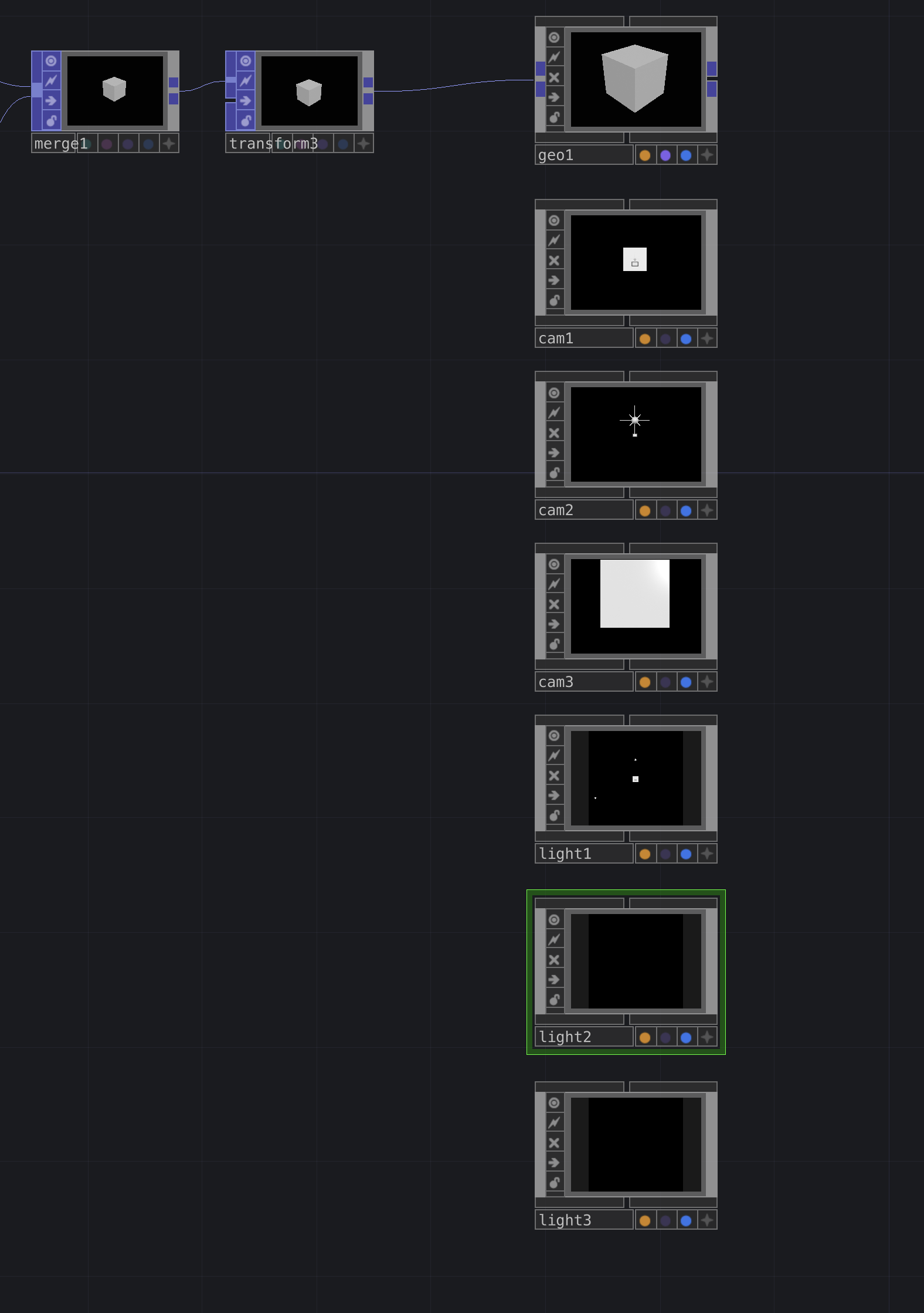 |
|---|
| Lights |
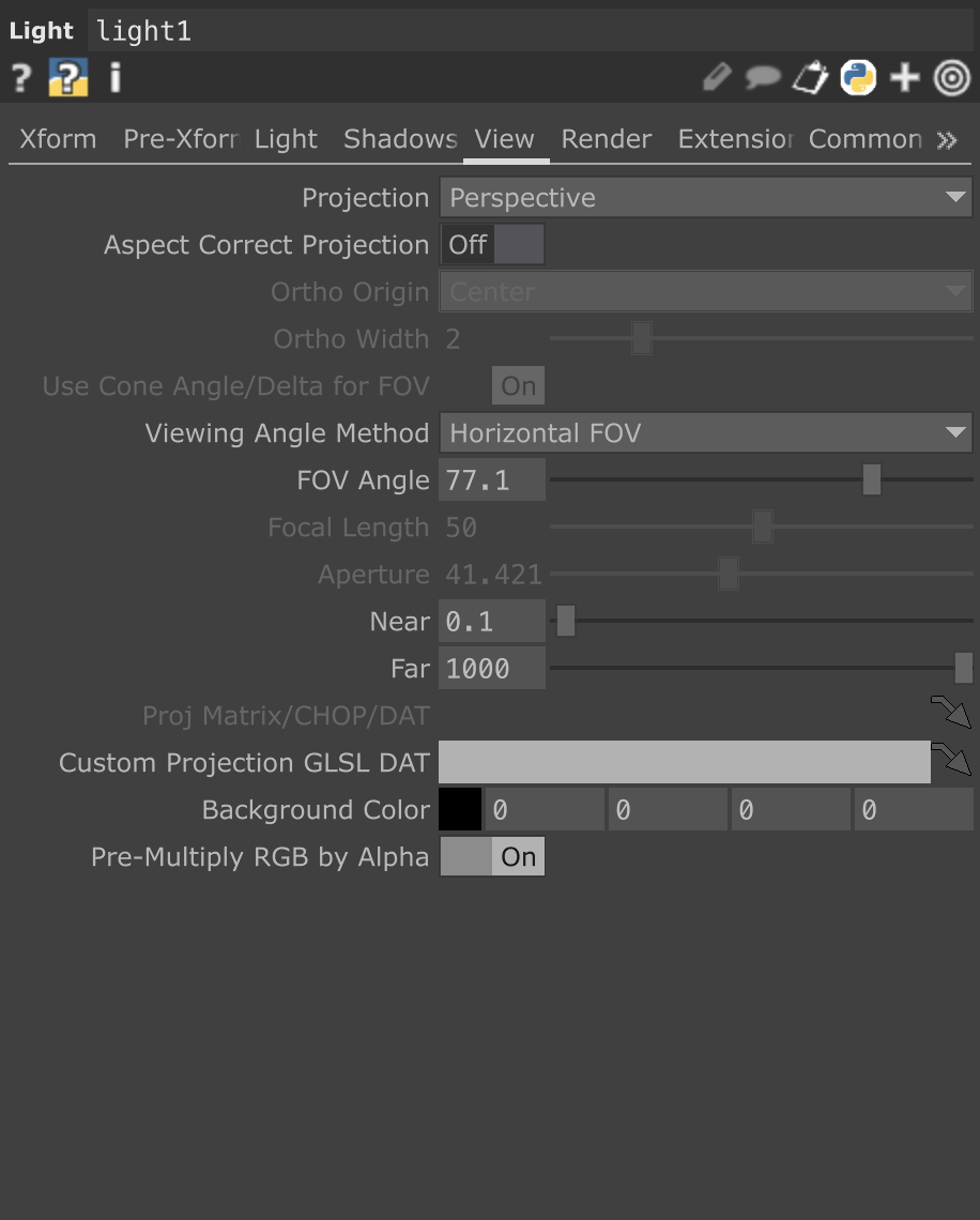
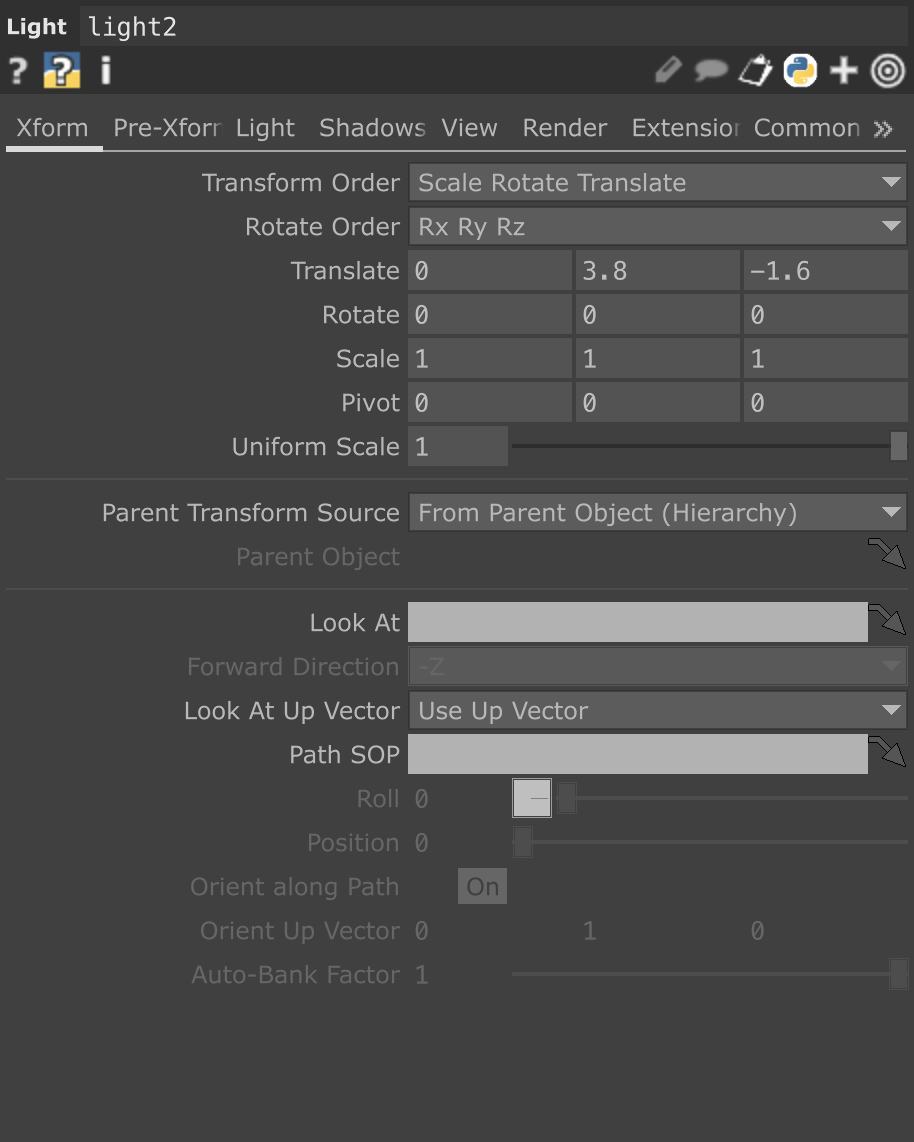
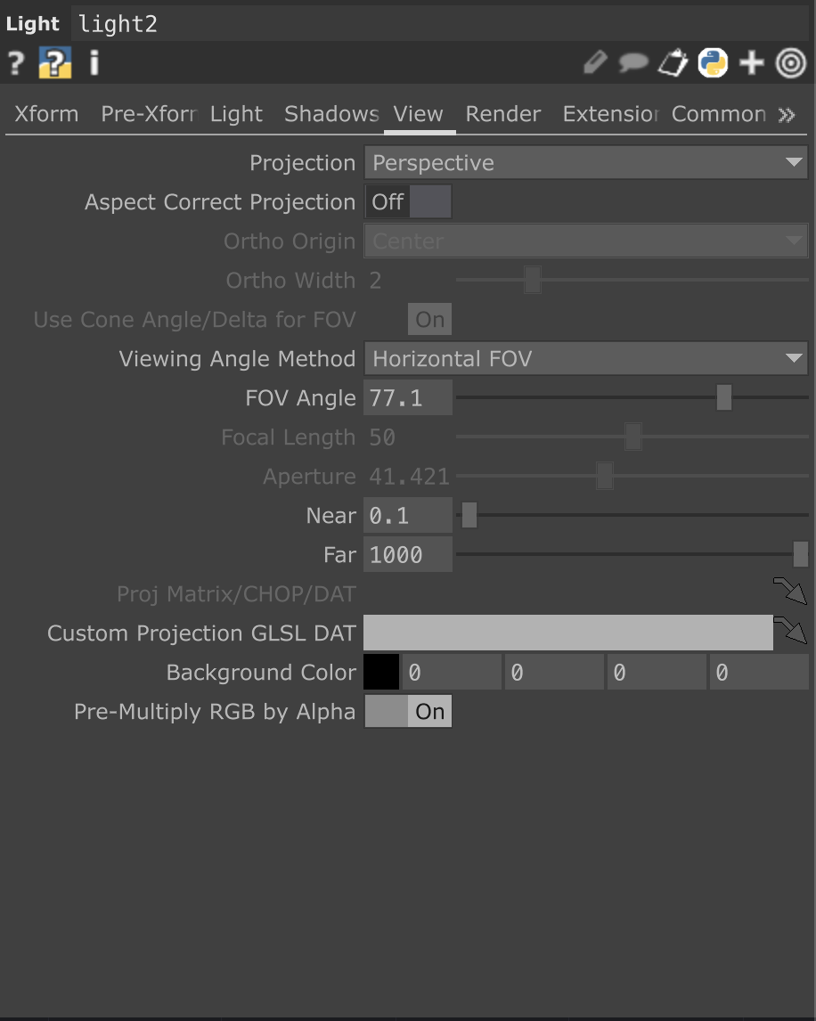
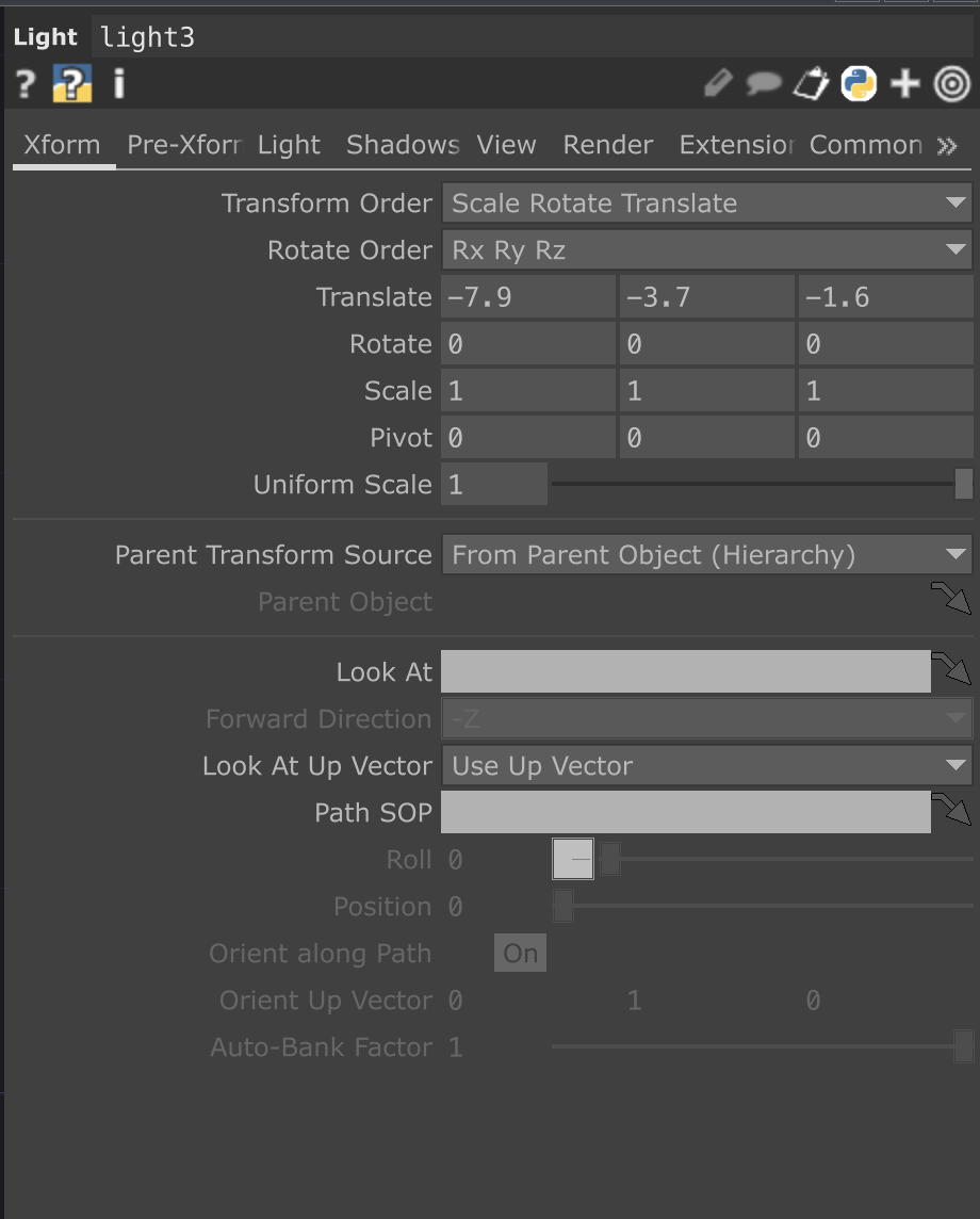
Light parameters are below:
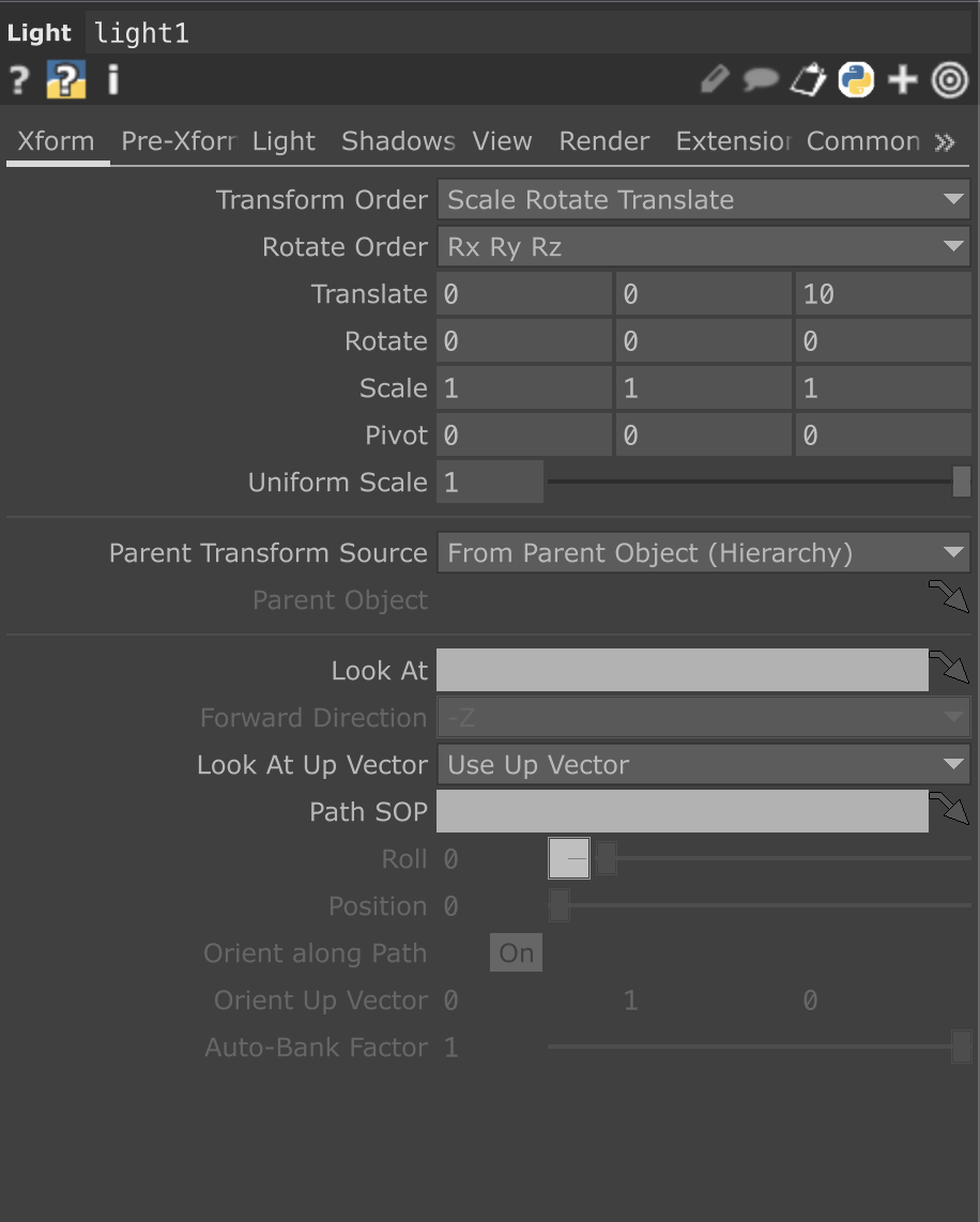 |
 |
|---|---|
| LIGHT1 XForm | LIGHT1 View |
 |
 |
|---|---|
| LIGHT2 XForm | LIGHT2 View |
 |
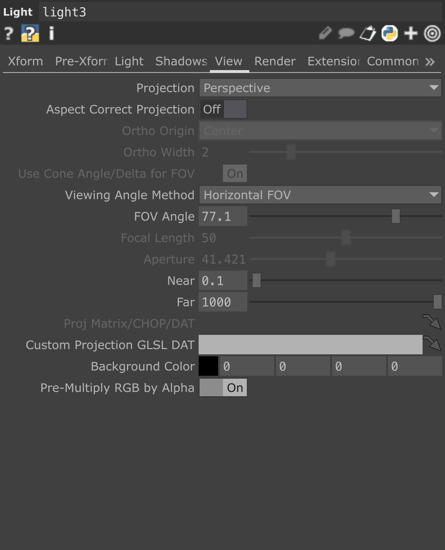 |
|---|---|
| LIGHT3 XForm | LIGHT3 View |
Now that all the cameras and lights are set up, we need a way to see the output, this is where the Render TOP comes in.
Create a Render TOP. Once you place it in the network, you’ll notice that several (but not all) of the components you just made automatically connect to it.
Select the Render TOP, then navigate to its parameters.
While keeping the Render TOP selected, move the network viewer until you can see the
constant1CHOP. Don’t click the node directly — instead, click the white star in its top-left corner to make it the active viewer.Go to the Common section in the Render TOP’s parameters. With the
constant1CHOP active, drag and drop the[resx, resy]channels into the Resolution fields and choose “CHOP Reference” when prompted.
 |
|---|
| Resolution |
Now, navigate back to the render1 TOP and copy + paste it two times to create three total Render TOPs.
For each new Render TOP, change the Camera(s) parameter to use its corresponding camera:
render1→cam1render2→cam2render3→cam3
 |
|---|
| Camera Setup |
To finish this section, we’ll add a material to our Geometry node.
This gives us greater control over how the boxes are rendered.
- Open the operator palette and navigate to the MAT section.
- Select the
Wireframematerial operator and place it near thegeo1node.
This material node should have the following parameters:
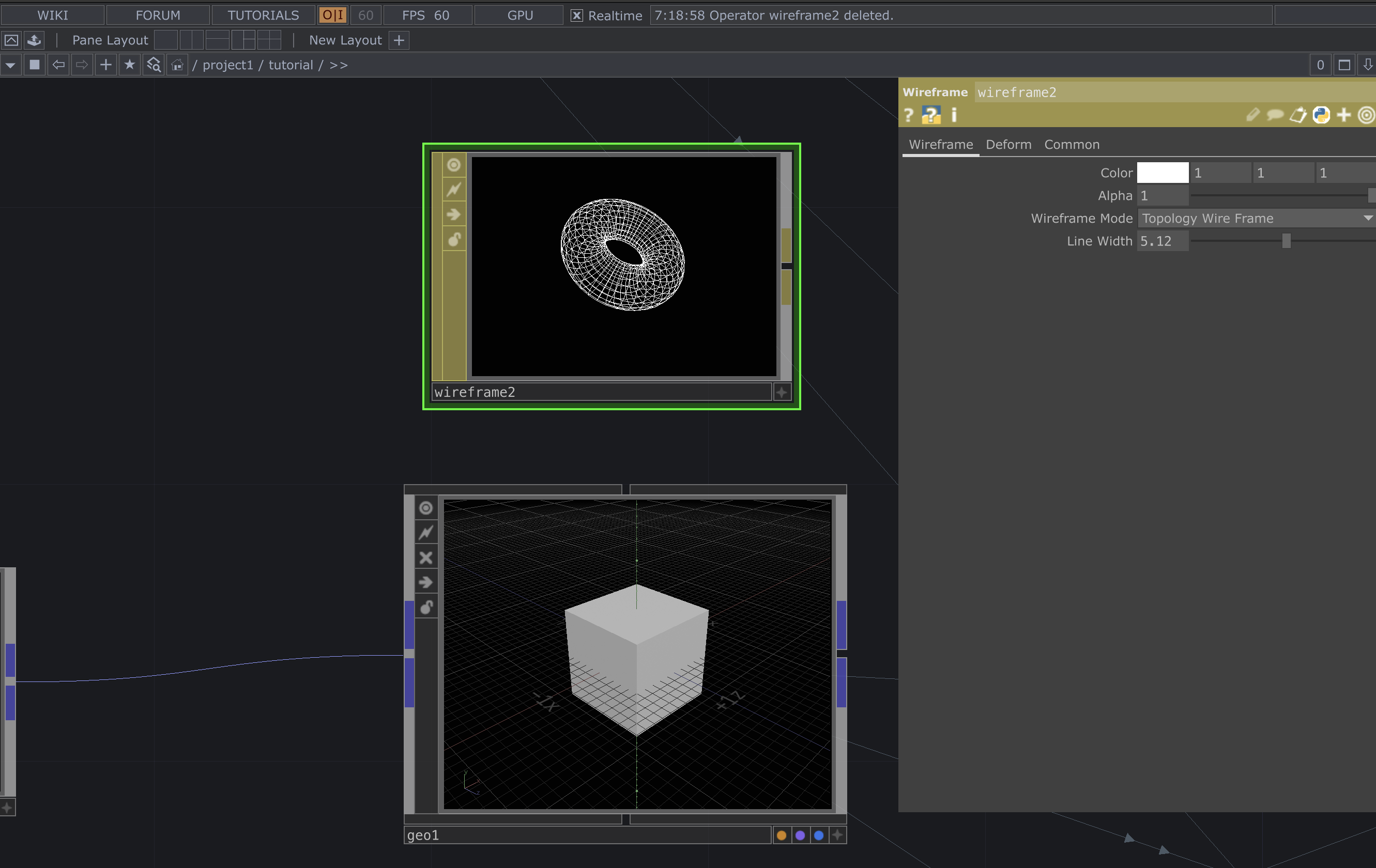 |
|---|
| Material |
After configuring the material, drag and drop the material node directly onto the geo1 Geometry node.
When prompted, select “Param: Material” to assign the wireframe material to the geometry.
 |
|---|
| Material |
Parameter Hookups
Just like we connected our resolution constants to the Render TOP, there are several other Constant CHOPs that need to be connected to different nodes in the network. These connections will help drive various parameters and maintain consistent control throughout the setup.
 |
|---|
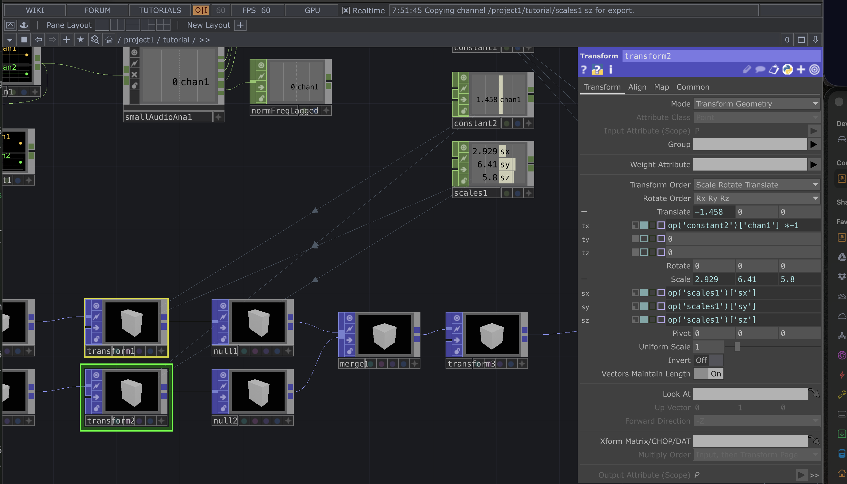
Constant2 need to be mapped to the translate parameter for both boxes as shown below, but one of those needs to be multiplied by -1 |
 |
|---|
| Next we will use the scales1 CHOP and connect those to the scale values in both of the transforms POP nodes we just modified. |
 |
|---|
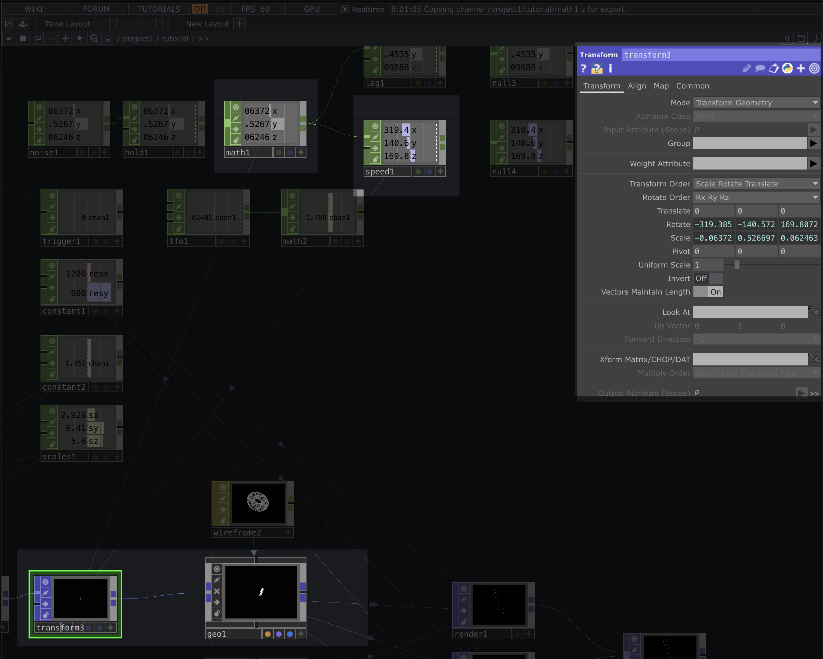
| On the last transform before going into the geometry node, we need to map the values from our speed and math CHOPs to the rotation and scale parameters respectivly |
 |
|---|
The math CHOP also needs to be hooked up the trigger and normFreqLagged * 200 in its Multi-Add section |
Post Processing
Now that we’ve created our rendering network and connected all the parameters, it’s time to start adding effects and post-processing to achieve the look and feel we’re going for.
- Add a Merge TOP and connect all three
rendernodes to it. - After the Merge, add a Null TOP.
- Click the blue display dot in the bottom-right corner of the Null, this will display the output as the background in your network viewer.
 |
|---|
| As a tip, you can multi-select and multiconnect nodes to each other depending on the node |
You should now see the shape moving on its own, while also reacting to changes in the audio frequencies.
Next, move the terminating Null TOP (the one at the end of the render chain) to make some space, enough to fit about 10 new nodes between the Switch and Null nodes. This is where we’ll continue adding our post-processing effects.
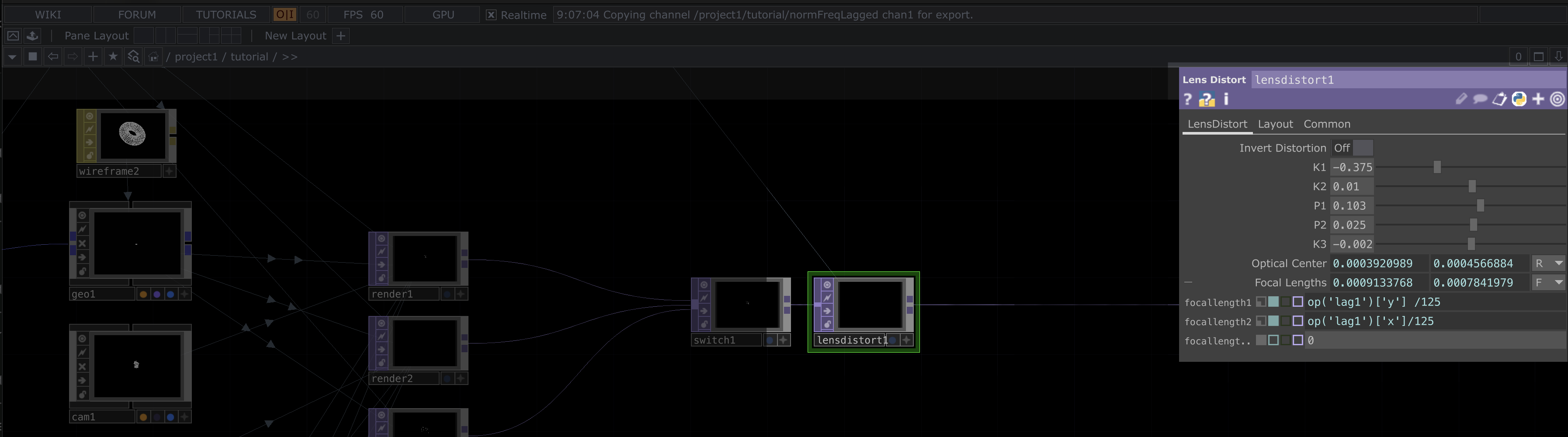
Now, add a Lens Distortion TOP between the Switch and Null TOPs. Once placed, connect it properly in the chain and adjust its parameters as shown in the reference images below.
 |
|---|
| Lens Distortion |
 |
|---|
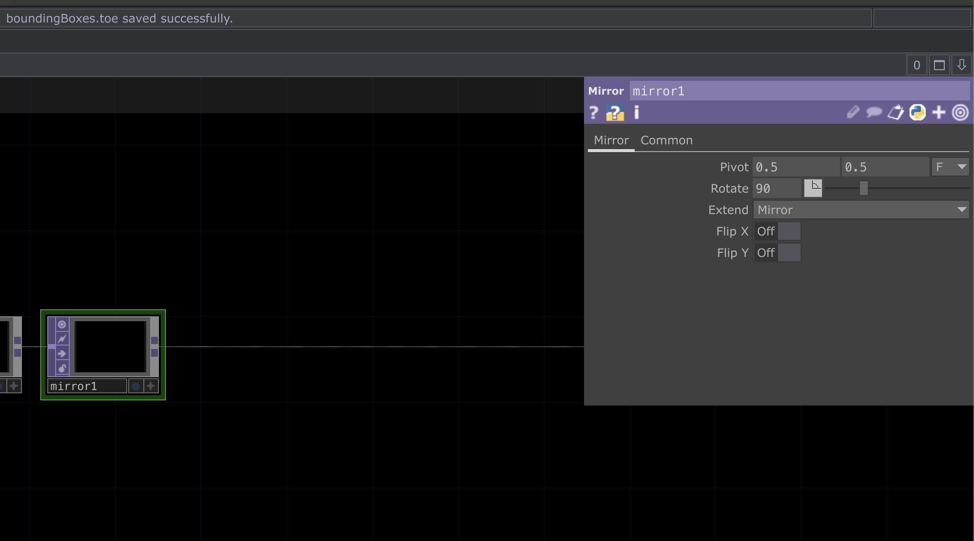
| Next add a mirror TOP with the following parameters |
 |
|---|
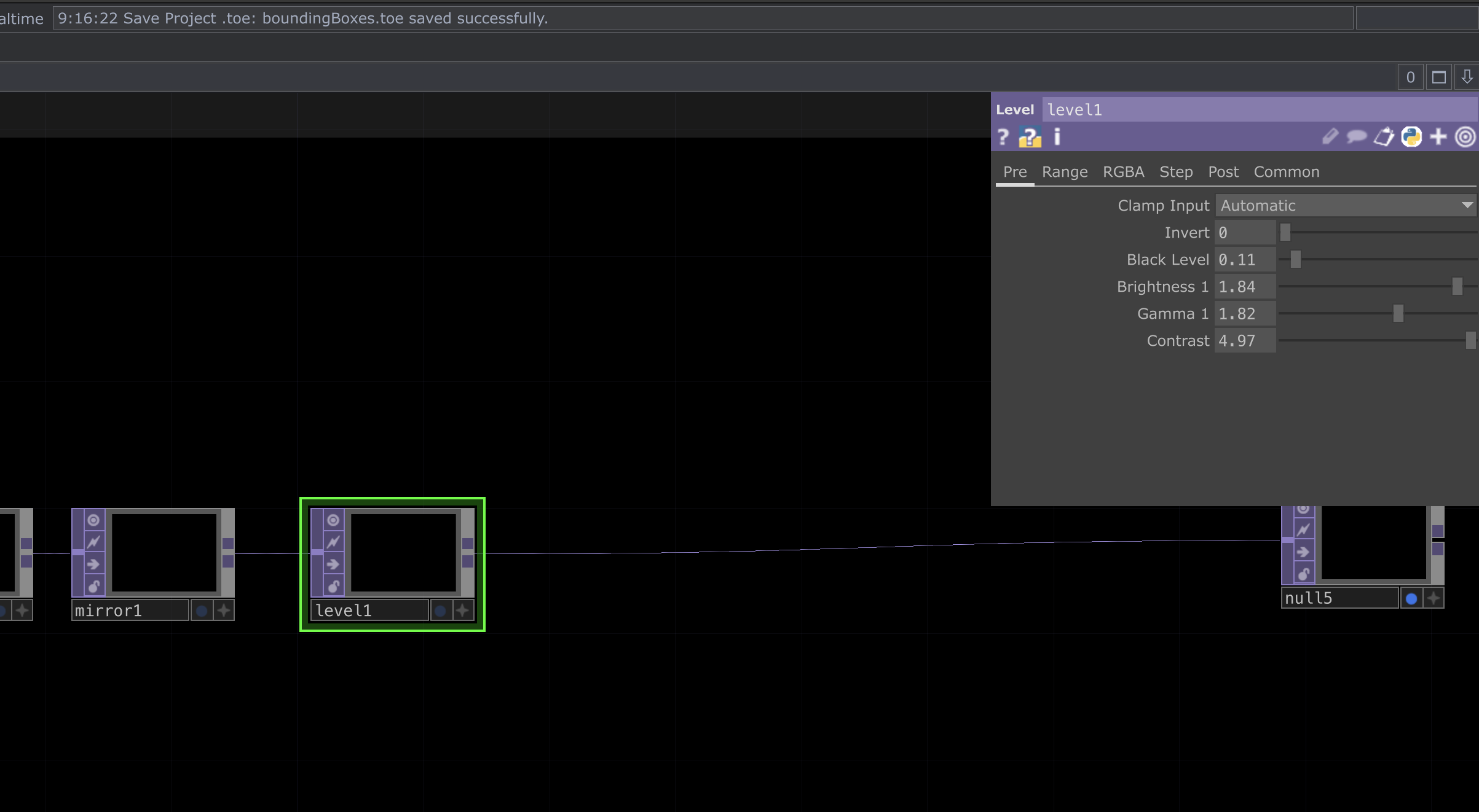
| Next add a level TOP with the following parameters |
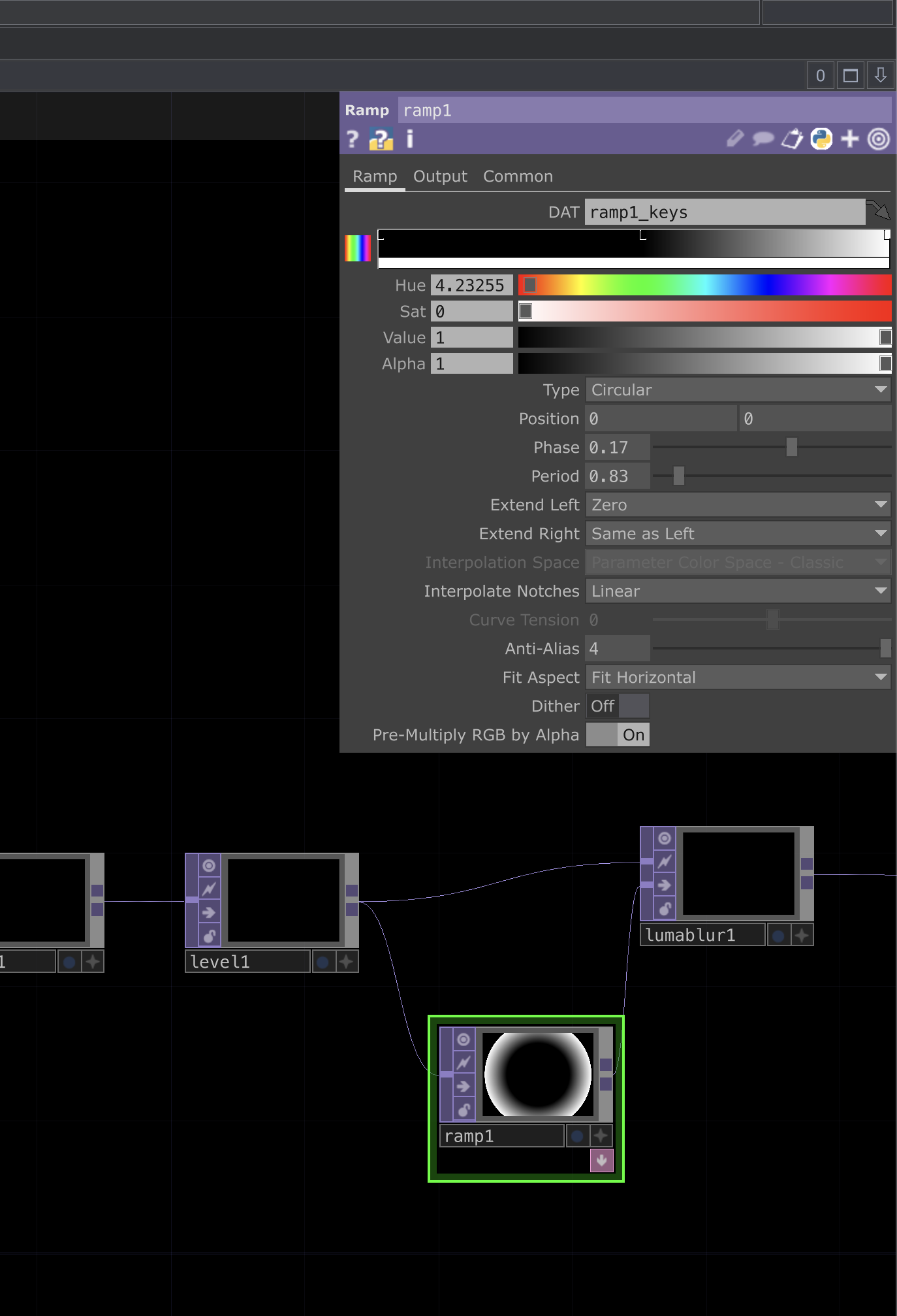
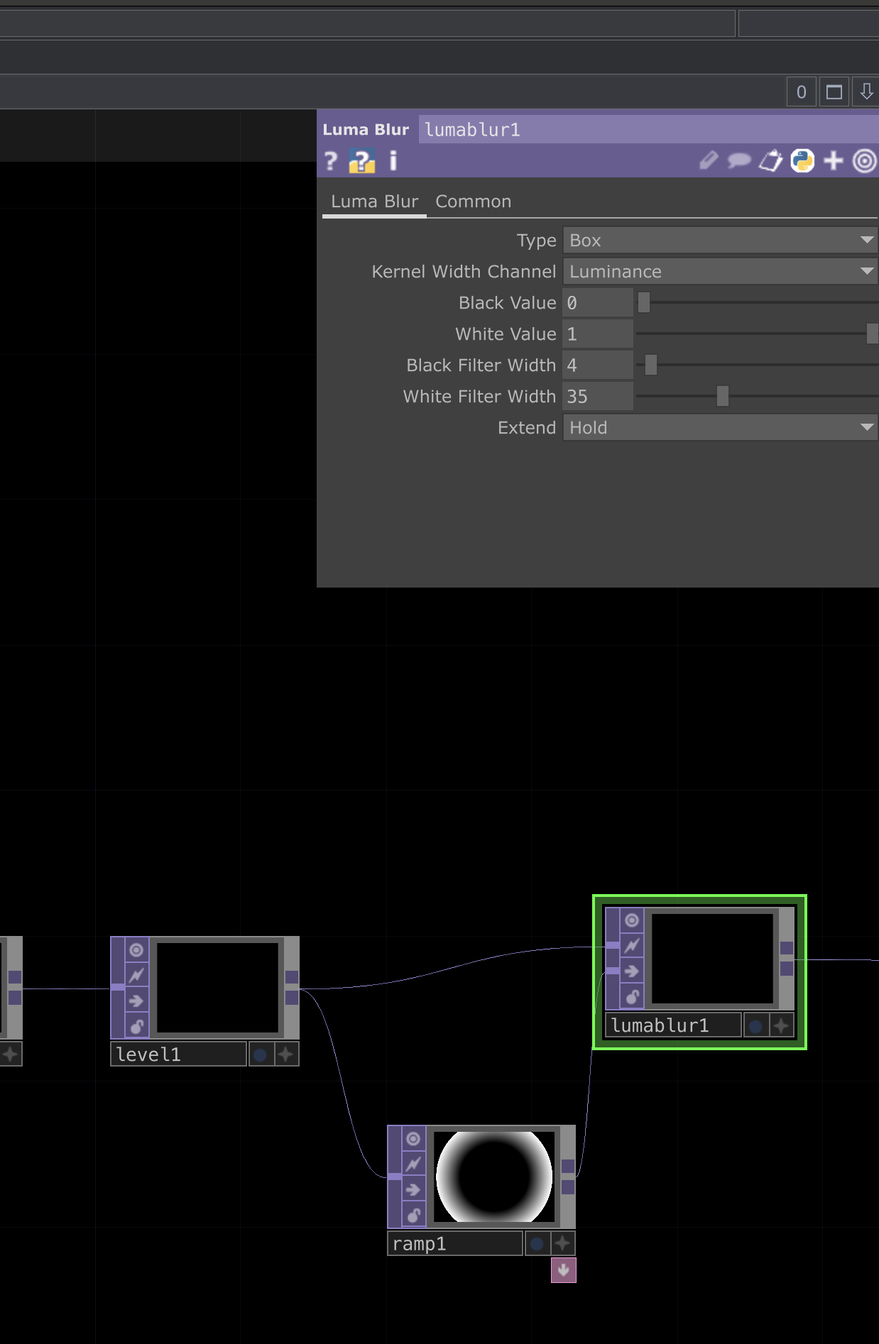
For the next step, we’ll be adding two TOPs, a Ramp TOP and a Luma Blur TOP.
These two will work together to add blending and depth effects to our render. Refer to screenshots below to see how they’re connected and what parameter values should be used for each.
 |
 |
|---|---|
| Ramp parameters | Luma Blur parameters |
 |
|---|
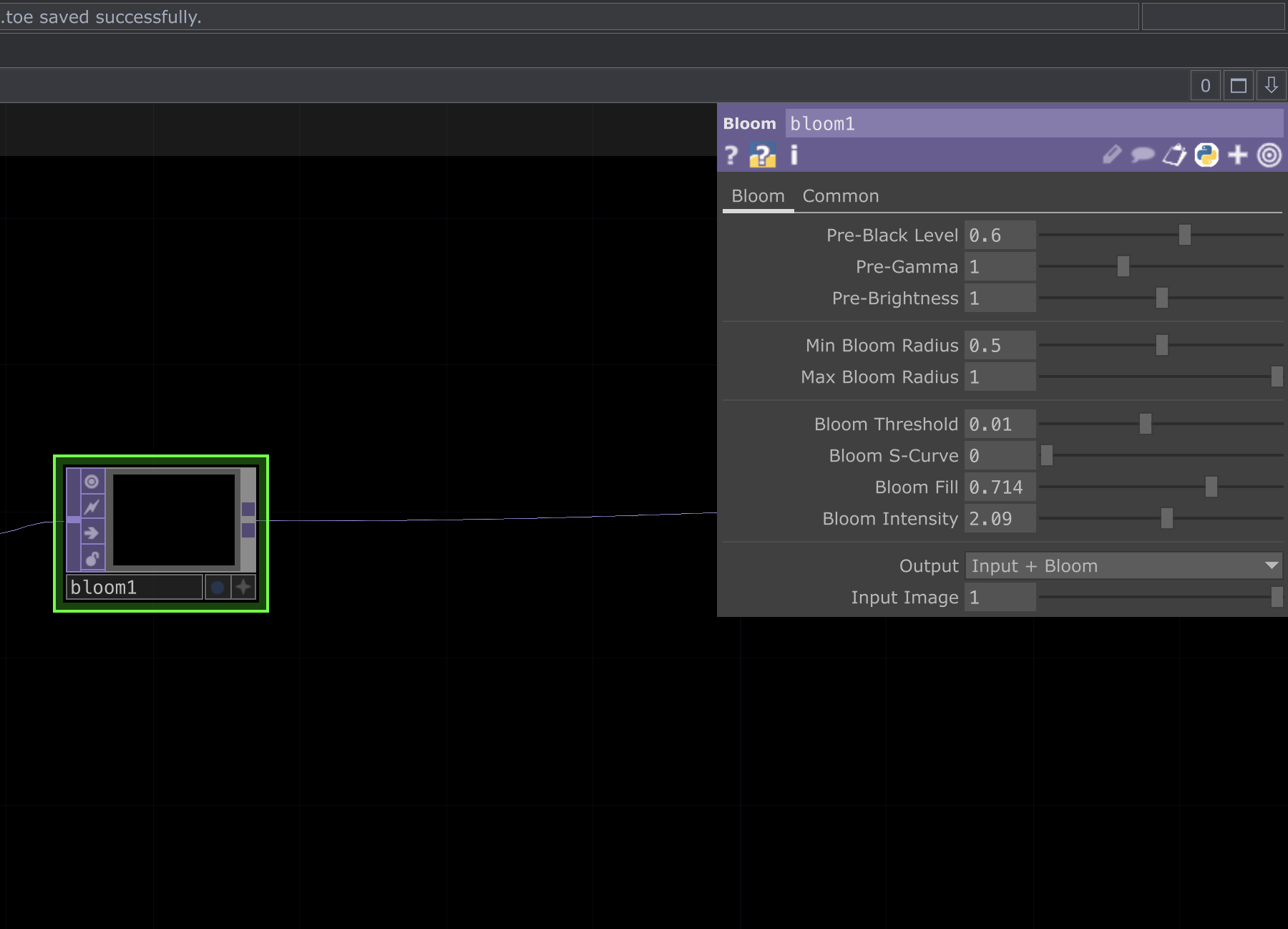
| Next add a bloom TOP with the above parameters |
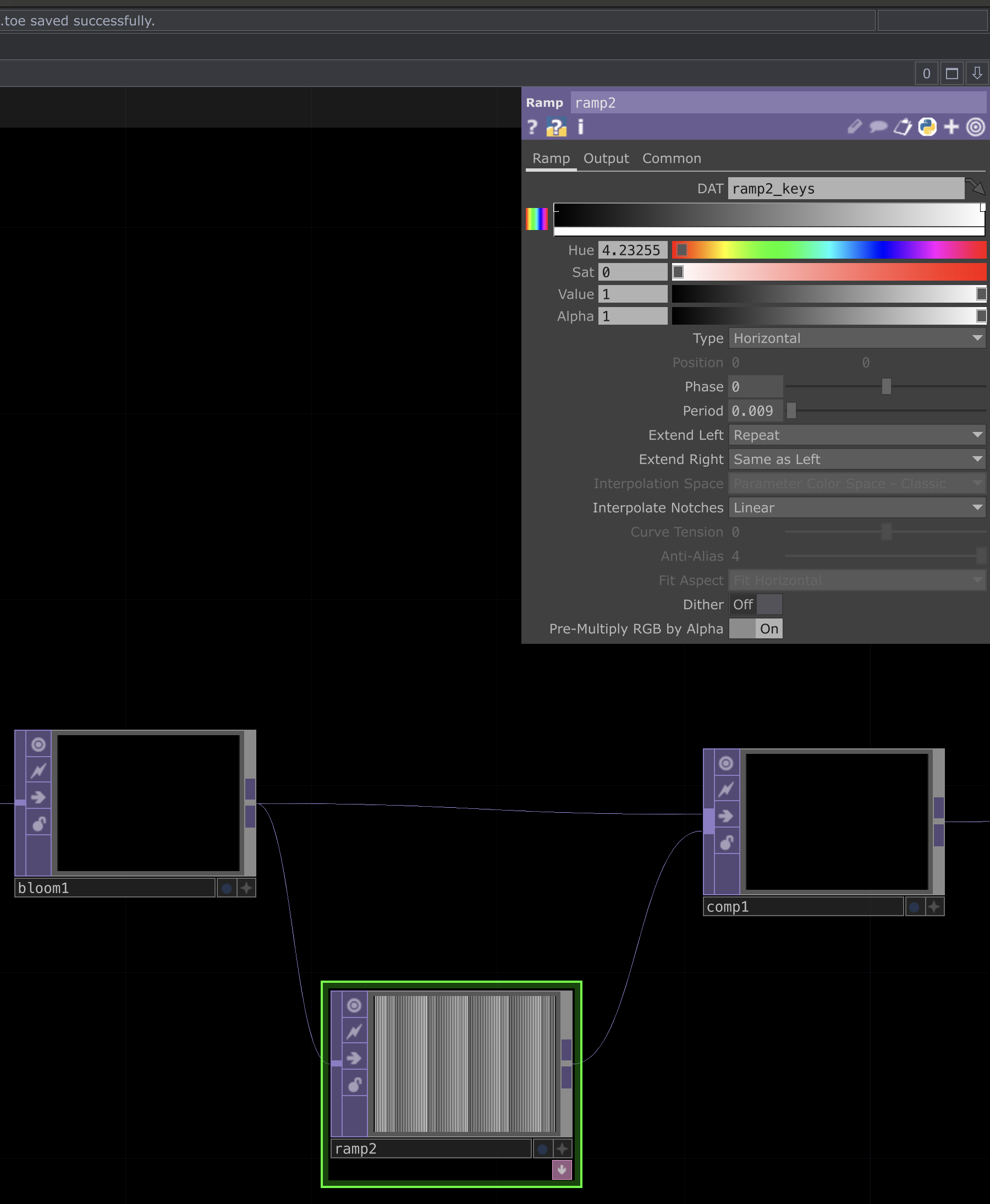
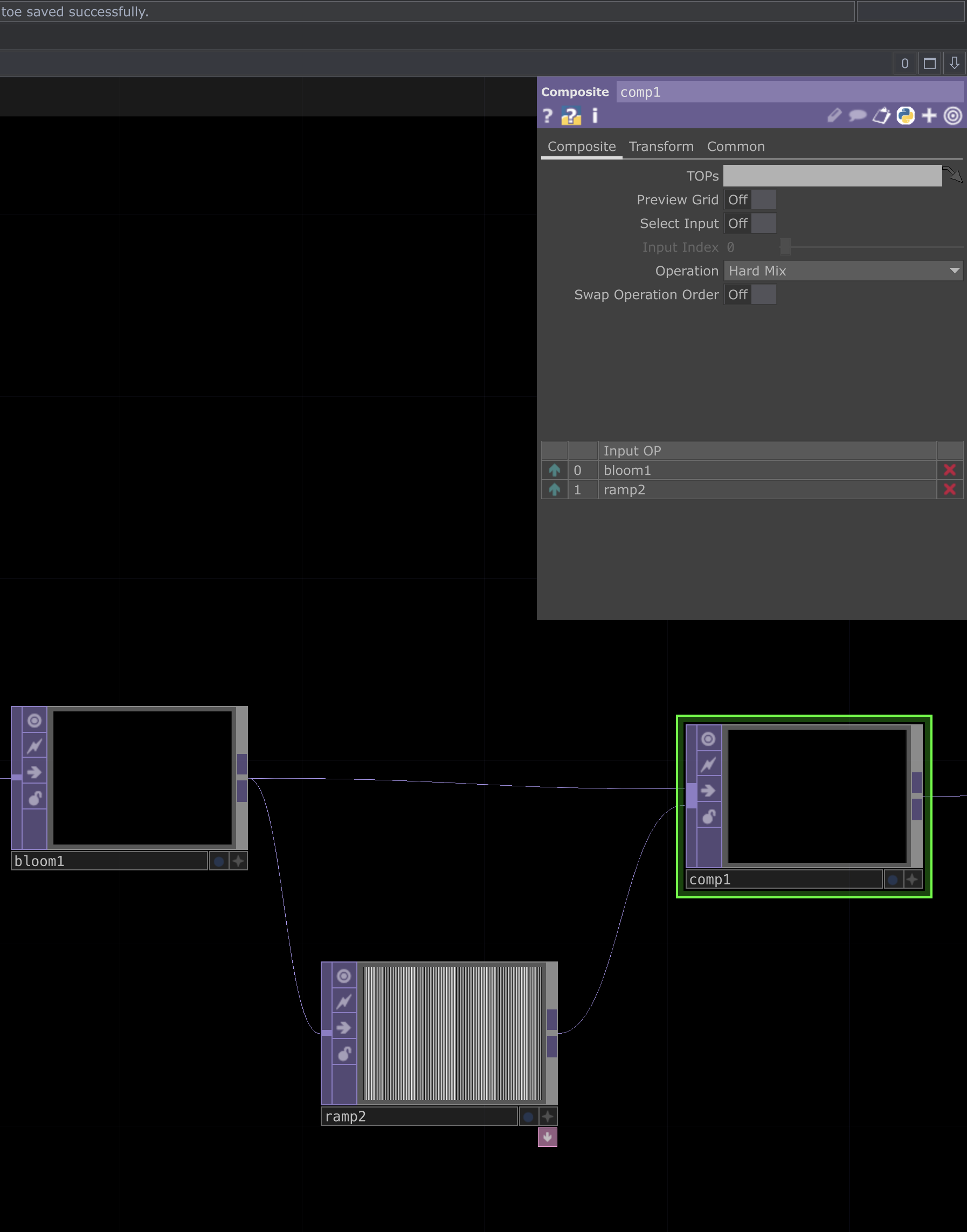
In this step, we’ll be adding two TOPs, a Ramp TOP and a Composite (Comp) TOP.
These nodes will help give a CRT like affect that I like. See below for how they’re connected and the parameter settings used for each.
 |
 |
|---|---|
| Ramp parameters | Comp parameters |
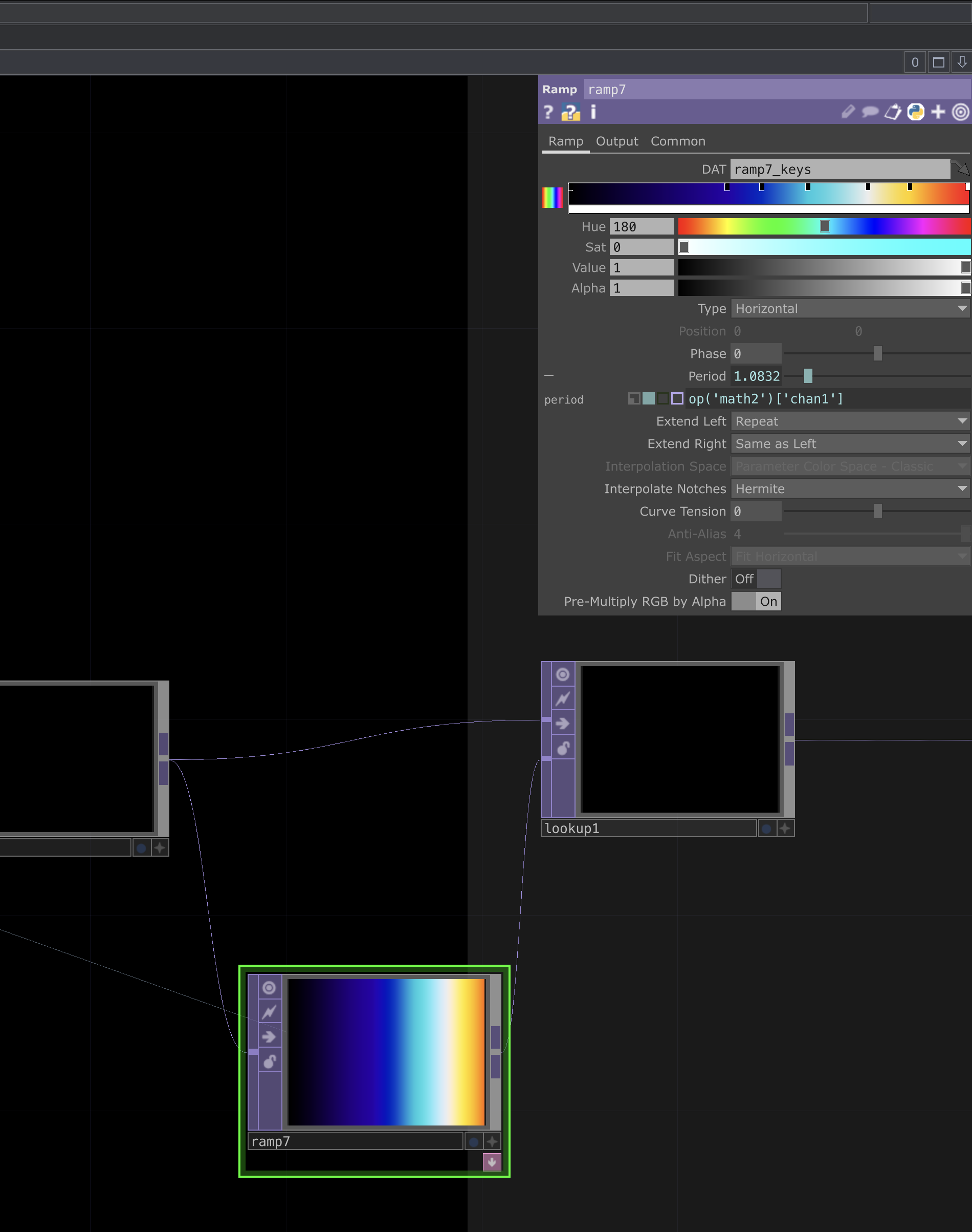
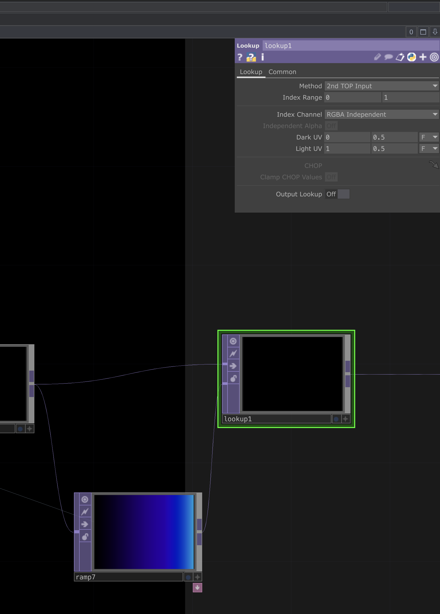
This next step involves adding two TOPs, where we’ll introduce color into our composition. Create a Ramp TOP and a Lookup TOP.
These will be used to map color values onto the visual, allowing us to control gradients and tone. See below to see how they’re connected and what parameters each should use.
 |
 |
|---|---|
| Ramp parameters | Lookup parameters |
Viewing, Exporting, and Recommendations for Expansion
After that last Lookup TOP, the visualization should be complete. You should see that the LFO CHOP is constantly changing which color we sample from the final Ramp TOP, and that the entire project is audio-reactive.
From here, feel free to tweak any or all values to achieve different results. A few common ones I like to adjust:
- Camera FOV
- Switching which Camera is used via the Switch TOP that all the Render TOPs feed into
- Box sizes
- Adding different shapes
To export this visual as a video, add a Movie File Out TOP and set the format/codec/framerate to suit your needs.
A .tox file containing the finished project is linked here in case you run into any issues.
 |
|---|
| Movie File Out |
Links to View My Own Version
You can check out my version of the finished visual here: